
User Manual Owner manual

Rockwell Automation Publication 1715-UM001C-EN-P - March 2014 3
Summary of Changes
This publication contains new and updated information. Changes throughout
this revision are marked by change bars, as shown to the right of this paragraph.
New and Updated
Information
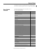
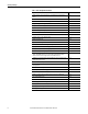
This table contains the changes made to this publication revision.
Table 1 - New and Updated Information
Topic Page
Updates to include SIL 2 operations with L7 ControlLogix® controllers 13
Studio 5000® Logix Designer™ application added throughout document and new
information about who can use this system
14
Using ControlLogix in SIL 2 Applications Safety Reference Manual added to Additional
Resources section
14
Added redundant 1715 adapter module and status indicator information 15
Added information about using a 1715 system in a SIL 2 application 16
Corrected drawing; added 1756-L7 controller and 1756-RM2 module; added reference
for DLR topologies.
20
Corrected drawing; added 1756-L7 controller and 1756-RM2 module 21
Network status indicator information 27
CIP messages 30
Required connections for duplex and simplex operation 31
Listen Only connections 32
Conformal coating is available on all 1715 modules 39
1715-A2A adapter base unit fuse graphic and removal and replacement information 42
Digital input termination assembly removal and replacement of fuses 47
Digital output termination assembly removal and replacement of fuses 48
Analog input termination assembly removal and replacement of fuses 49
Power requirements 53
1715 chassis firmware upgrade; power recycle needed 54
ControlFLASH™ revision number 54
Power requirements for PELV/SELV 63
Correction to system power graphic 76
Digital Input diagram correction-standard inputs 80
Short circuit information 79
Digital Input diagram correction-line monitored inputs. Added reference for calibration
drift checks.
81
Corrected digital input termination assembly graphics 85
Added Attention table for inductive loads 87
Added missing arrow on 1715-OB8DE function block diagram, going from the Control B
box to the Output Control.
88
Diagram correction-digital outputs 93
Damaging pins when inserting/removing I/O modules under power can fault the system 95
Corrected analog inputs graphic by removing footnote numbers on voltage 96