
User Manual Owner manual


Rockwell Automation Publication 1715-UM001C-EN-P - March 2014 283
1715-IB16D Digital Input Module Diagnostics Appendix C
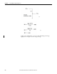
Off Condition
For an off condition, we need to add a new resistor to the formula. We already
know R2 is 3.9 k
so we can use that, too.
In this example, 15.4 k
is a close standard value, so we use 15 k, which changes
the voltage slightly, but not enough to make us change our range.
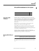
Calibration Drift Checks
The 1715I/O analog modules are calibrated at the factory with a default
calibration. As time passes, the electrical specifications of various electronic
components of your analog module drift.
To make sure the best possible accuracy in measurements made by your analog
input module and signals generated by your analog output module are
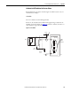
Shield
(if used)
Terminal
Blocks
OV
20Ω
100Ω
50 mA
4.99kΩ
Termination
Assembly
+24V dc
R1
R2
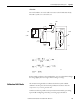
45678
5 V DC
5.1K
SW1
3.9k
45684