
User Manual Owner manual

276 Rockwell Automation Publication 1715-UM001C-EN-P - March 2014
Appendix C 1715-IB16D Digital Input Module Diagnostics
Calculate Threshold and
Resistor Values
To arrive at the correct diagnostic settings, the user must know one of the two
values—either the threshold values or the resistor values, and then calculate the
other set of values from the known values.
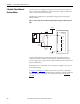
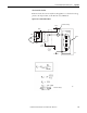
The following example shows a typical EOL arrangement for an Emergency
Shutdown Device.
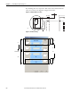
Figure 74 - Field Loop Circuit for Line Monitored Digital Input for Emergency Shutdown Systems
(ESD)
To better understand, the user must realize that by virtue of R1 and R2, in
combination with the module’s internal impedance and field switch position,
various voltage levels are produced at the input terminal that can be characterized
by the threshold values.
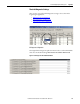
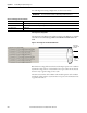
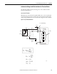
Knowing the resistor values allows you to calculate the voltage levels to arrive at
the threshold settings.
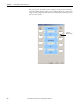
Use Figure 75
and Figure 76, and the resistor values you choose. to determine
how the system responds to various field wiring conditions, so that the threshold
values can be set. For our example, we used the resistor values in Table 60 on
page 274.
Shield
(if used)
Terminal
Blocks
OV
20Ω
100Ω
50 mA
4.99kΩ
Termination
Assembly
+24V dc
R1
R2
45678