
User Manual Owner manual


246 Rockwell Automation Publication 1715-UM001C-EN-P - March 2014
Chapter 8 Redundant I/O System Diagnostics
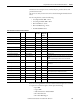
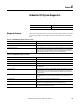
Table 51 - 1715-OB8DE Module Diagnostic Features
Feature Description
Redundancy level Simplex or duplex.
Redundancy status The status of each module of a duplex pair is available in the input tag.
Change-of-state transport The connection trigger for the discrete output is change-of-state. Data is produced when output
data is consumed, or when diagnostic data changes state, or at the Requested Packet Interval.
Unlike the discrete input module, change-of-state production cannot be disabled for the discrete
output module.
No load detection A fault is indicated when no load is detected while the output point is in the off state. No load
detection can be disabled to prevent alarms from appearing for unused points.
Short circuit detection A fault is indicated when a short circuit/over current condition is detected. The fault indication is
reset when the following occurs.
1. Point is commanded off.
2. A short reset service is sent to the module.
3. A reset is done through a bit in the output tag.
Diagnostic latch When latching is enabled, diagnostic alarms are latched until they are reset. This aids in detecting
intermittent issues. For output modules, latch reset can occur either through messaging or through
a member of the output tag.
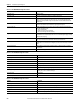
Fault mode When a connection from a controller exists, and the connection is interrupted, the module outputs
take on a user-selected state. This Fault mode is either Off, On or Hold Last State.
Program mode When a connection from a controller exists, and the controller is not in Run mode, the module
outputs take on a user-selected state. This Program (a.k.a. ‘Idle’) mode is either Off, On or Hold Last
State.
Program to fault enable When enabled, the outputs assume the fault value when a communication fault occurs while in
Program mode.
ReadBack The state of each output point is reflected in the input tag.
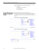
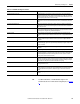
Table 52 - 1715-IF16 Module Diagnostic Features
Feature Description
Redundancy level Simplex or duplex.
Redundancy status The status of each module is available in the input tag.
Input range Fixed as 0…20 mA.
Wiring Single-ended only.
Data format Read-only.
Scaling Support choice of signal and engineering range.
Underrange overrange Diagnostic alarms are provided when the signal goes above or below what the module is capable of
detecting. (Zero or less is considered underrange.)
Rolling timestamp 1 ms resolution.
Real time sample rate Fixed RTS.
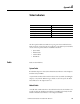
Table 53 - 1715-OF8I Module Diagnostic Features
Feature Description
Redundancy level Simplex or duplex.
Redundancy status The status of each module is available in the input tag.
Input range Fixed as 0…20 mA.
Scaling Support choice of signal and engineering range.
ReadBack The state of each output point is reflected in the input tag.