
User Manual Owner manual

Rockwell Automation Publication 1715-UM001C-EN-P - March 2014 225
Using SIL 2 Add-On Instructions with 1715 Redundant I/O Modules Chapter 7
A SIL 2 Reset can be used to reset this condition.
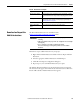
The following figures illustrate how the Add-On Instructions work with input
and output data.
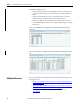
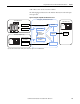
Figure 65 - Diagram of Input Module Add-On Instruction
IO BASE
1715-A310
CH1
CH1
CH1
CH1
CH1
CH1
CH1
CH1
TERMINAL IDENTITY
AOTA
Dual.
CH1
CH1
CH1
CH1
CH1
CH1
CH1
CH1
TERMINAL IDENTITY
AOTA
Dual.
CH1
CH1
CH1
CH1
CH1
CH1
CH1
CH1
TERMINAL IDENTITY
AOTA
Dual.
1715-AENTR
1715-AENTR
1715-A2A
1715-A3IO
1715-IF16
1715-IF16
1715-
TAS IF 16
1715-
TAS IF 16
IF16_Duplex_SIL2 Add-On Instruction
1715-IF16 Data Packet
SIL 2 Check Data
1715-IF16 Configuration Tag
Safe State Defaults
Module Configuration
Check Data
SIL 2 Check Data
Module Configuration
Check Data
Safe State Defaults
Input Data
Input Data
Reconciled
Input Data
The Add-On
Instruction verifies
the check data.
D
at
a
i
s
val
i
d
.
D
a
t
a
i
s
n
o
t
v
a
l
i
d
.
1756 Controller Tags
Reconciled
Input Data
Important: The 1715-IF16 module is shown, but the example also applies to the 1715-IB16D module.