
User Manual Owner manual

194 Rockwell Automation Publication 1715-UM001C-EN-P - March 2014
Chapter 5 Configure the Redundant I/O System
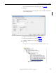
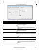
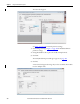
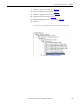
The Configuration tab appears.
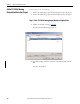
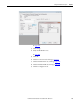
10. Click the Limits tab.
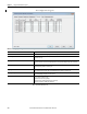
Table 37 - Analog Output Configuration Parameters Duplex Mode
Parameters Description
Channel Click the channel number to configure parameters for the specified channel (0…15).
Current Range Displays the current range (0…20 mA) for the channel.
This field is read-only.
Low Signal Check the Low Signal value for the channel (between 0.0…20.0 mA). The default is
4.0 mA. This value must be less than the High Signal value. Low Signal and Low Engineering values are shown in
pairs.
Low Engineering Check the Low Engineering value for the channel (between -9999999…99999999). The default is 0.0. Low Signal
and Low Engineering values are shown in pairs.
High Signal Check the High Signal value for the channel (between 0.0…20.0 mA). The default is 20.0 mA. This value must be
greater than the Low Signal value. High Signal and High Engineering values are shown in pairs.
High Engineering Check the High Engineering value for the channel (between -9999999…99999999). The default is 100.0. High
Signal and High Engineering values are shown in pairs.
Hold for Initialization Set the channel to hold, or not change, until initialized with a value within 0.1% of full scale of its current value
when one of these conditions occurs:
• Module initial connection (powerup)
• Module transition from Program mode back to Run mode
• Module reestablishes communication after fault.