
User Manual Owner manual

Rockwell Automation Publication 1715-UM001C-EN-P - March 2014 183
Configure the Redundant I/O System Chapter 5
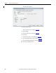
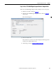
The Configuration tab appears.
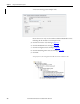
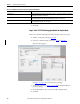
11. Click the Fault/Program Action tab.
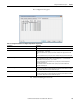
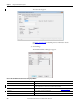
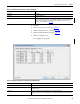
Table 33 - Configuration Parameters for Digital Output Module in Duplex Mode
Parameters Description
Point Click the point number to configure parameters for the specified point (0…7).
No Load Detection By default, the header checkbox is selected and all points (0…7) are selected. If the header checkbox
is cleared, all points (0…7) are cleared.
To specify no load detection for a specific point, check the checkbox in the appropriate row for that
point.
To clear no load detection for a specific point, clear the checkbox in the appropriate row for that point.
Latch No Load Diagnostics Choose if load fault alarms are latched until reset (including Open Wire Detection and Short Circuit
detection). By default, the header checkbox is selected and all points (0…7) are selected. If the
header checkbox is cleared, all points (0…7) are cleared.
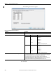
To select load fault alarms are latched until reset for a specific point, check the checkbox in the
appropriate row for that point.
To clear load fault alarms are latched until reset for a specific point, clear the checkbox in the
appropriate row for that point.
Reset Latched Diagnostics Click Reset to reset the diagnostic latch service.
When online and in Program mode, Remote Program mode, Run mode, the Reset button is enabled
for a point. When offline, the Reset button is dimmed for a point.
Reset Fuse Click Reset to reset the fuse reset short/overload service.
When online and in Program mode, Remote Program mode, Run mode, the Reset button is enabled
for a point. When offline, the Reset button is dimmed for all points.