
User Manual Owner manual


18 Rockwell Automation Publication 1715-UM001C-EN-P - March 2014
Chapter 1 Redundancy System Overview
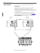
Module Positioning in the 1715 Redundant I/O System
There are 26 total slot positions in the system numbered from 0…25. The first
two positions always contain the redundant adapter module pair, in slots 0 and 1.
The remaining positions begin numbering at slot 2 and contain the I/O modules,
ending at slot position number 25. Any combination of simplex or duplex I/O
module pairs can be used in the I/O base units. See Tab le 3
for a sample of what a
system could look like.
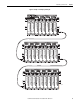
Expansion cables can be used to connect base units, as shown in Figure 1 on
page 19.
TIP
The sample system configuration in Example 1 does not match the system
layout displayed in Example 2. These are different examples of possible
configurations you can have for your system.
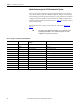
Table 3 - Example 1 - A Sample System Configuration
System Slot Number Base Unit Type Module Position/Slot Number by Base
Unit Type
Module Designation
0 Adapter 0 Adapter A
1 Adapter 1 Adapter B
2 I/O 01 First I/O base unit Module A of first duplex pair
3 I/O 02 Module B of first duplex pair
4 I/O 03 Module A of second duplex pair
5 I/O 04 Second I/O base unit Module B of second duplex pair
6 I/O 05 First simplex module
7 I/O 06 Module A of third duplex pair
8 I/O 07 Third I/O base unit Module B of third duplex pair
9 I/O 08 Second simplex module
10 I/O 09 Third simplex module
11…25 I/O 10…24 Fourth…eighth I/O base unit Any combination of simplex/duplex pair modules