
User Manual Owner manual

162 Rockwell Automation Publication 1715-UM001C-EN-P - March 2014
Chapter 5 Configure the Redundant I/O System
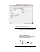
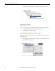
4. Click Change.
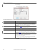
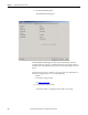
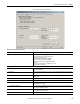
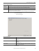
The Module Definition dialog box appears.
5. Click OK.
Table 24 - Module Definition Parameters
Parameters Description
Series Module series letter.
Revision Major: Choose the revision of the module.
Minor: Set the module’s minor revision. This field is enabled while offline, and while in the Program, Remote
Program, and Remote Run modes. It appears dimmed when in Run mode, or when electronic keying is set to
Disable Keying.
For SIL 2 applications, choose version 2.01.07 or later for 1715-AENTR modules.
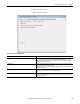
Electronic Keying Electronic Keying, see Appendix B.
Valid values are Compatible Module (default), Exact Match, or Disable Keying.
Connection Leave as ‘Data’ - Listen Only is not supported.
Redundant Always Yes.
SIL 2 Safety Choose No if SIL 2 operation is not required.
Choose Yes to enable SIL 2 operation. The safety pull-down menu appears only if using Add-on Profile version
2.01.007 or later. Two new tabs are available for SIL 2 configuration if you choose Yes. For information on SIL 2
configuration, see Chapter 6
.
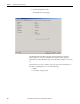
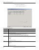
Chassis Size Choose the chassis size you want to use: 5,8,11,14,17,20,23,26.
The chassis size is a function of the number of bases installed in your system, which come in either groups of three
slots per base for I/O bases; and two slots per base for the redundant adapter base.
All slots in the chassis do not have to be populated.
To extend the size of a chassis, its size must be consistent with the number of base slots used. The minimum
chassis size is 5 slots, built from one 2-slot adapter base and one 3-slot I/O base.