
User Manual Owner manual

Rockwell Automation Publication 1715-UM001C-EN-P - March 2014 119
Installation Instructions Chapter 2
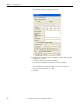
The following status indicators light depending on which module you are
installing. This is a quick installation reference. For more detailed status indicator
information, see Appendix
A.
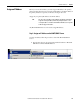
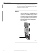
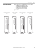
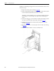
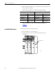
7. Turn the locking screw on the front of the module a 1/4 turn clockwise to
lock, referring to page 110
.
• The 1715-IB16D digital input module’s Redundancy Status indicator
shows RED when the screw is locked.
• The 1715-IF16 analog input module’s Redundancy Status indicator
shows RED when the screw is locked.
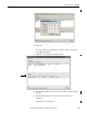
The module enters its start-up sequence. This takes approximately 3
seconds.
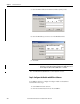
If the module is the first module in a TA group with a running adapter, it
displays the following status indicators. See Table 16
.
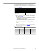
Table 15 - Start-up Sequence
1715-IB16D, 1715-OB8DE, 1715-IF16, and 1715-OF8I Modules
Indicator Status
Module Status Green
Redundancy Status Off
Network Status Red
Channel 0…7, 8…15 Off
Table 16 - First Module in TA Group
1715-IB16D, 1715-OB8DE, and 1715-IF16
Modules
1715-OF8I Module
Indicator Status Indicator Status
Module Status Green Module Status Green
Redundancy Status Green Redundancy Status Red to steady green
Network Status Amber Network Status Amber
Channel 0…7, 8…15 Off Channel 0…7 Off