
User Manual Owner manual

110 Rockwell Automation Publication 1715-UM001C-EN-P - March 2014
Chapter 2 Installation Instructions
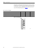
The following status indicators light. This is a quick installation reference. For
more detailed status indicator information, see Appendix
A.
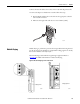
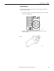
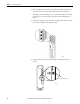
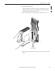
8. Turn the locking screw on the front of the module a 1/4 turn clockwise to
lock, by using a 9 mm screwdriver.
Each module has a locking screw that secures it to its base unit. The
module has an interlock that detects when a module is locked or unlocked.
For information about the Reset button’s functionality, see Reset Button on
page 255.
Table 14 - Start-up Sequence
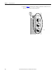
1715-AENTR Adapter Module
Indicator Status
Module Status Steady green
Redundancy Status Flashes, then steady green
Network Status Off
Rack Status Off, then steady green
Ethernet 1 Dependent on Ethernet connection status
Ethernet 2 Dependent on Ethernet connection status
IMPORTANT
Modules run only in the locked position.
1/4 Turn
To Lock Postion
Rack Status
Ethernet 1
Ethernet 2
Module Status
Redundancy Status
Network Status
1715-AENTR
ADAPTER
Reset
32083-M