
User Manual Owner manual

104 Rockwell Automation Publication 1715-UM001C-EN-P - March 2014
Chapter 2 Installation Instructions
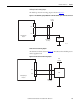
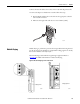
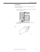
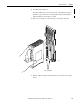
The legend for the coding pegs showing the peg positions is shown on the lower
left of the adapter base unit and on each I/O termination assembly. The positions
are numbered 1…6. The three coding pegs are lettered A, B, and C with A being
on the top. Each peg, or key, is fitted in the base unit so that the index recess is
next to the relevant numbered position. See Figure 56
.
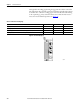
Figure 56 - Inserted Coding Pegs
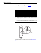
Table 13 - Allocations of Coding Pegs
Application Key A Key B Key C
1715 Adapter Base Unit 1 1 1
1715 Digital Input Termination Assemblies 2 1 1
1715 Analog Input Termination Assemblies (for analog input modules) 2 1 3
1715 Digital Output Termination Assemblies (for digital output modules) 3 1 1
32064-M