
User Manual Owner manual

Rockwell Automation Publication 1715-UM001C-EN-P - March 2014 103
Installation Instructions Chapter 2
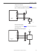
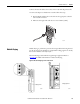
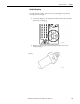
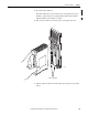
Connect the network cables to the sockets on the 1715-A2A adapter base unit.
To connect the adapter to the Ethernet network, follow these steps.
1. Insert the RJ45 modular jack on the cable into the appropriate socket for
each network connection.
2. Make sure the length of the cable does not exceed 100 m (328 ft).
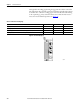
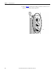
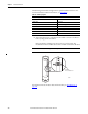
Module Keying
Module keying, or polarization, prevents the wrong module from being inserted
into the wrong base unit. Modules are supplied with coding pegs that are already
fitted, so the modules are already ‘keyed’.
Electronic Keying is used within the Logix Designer application. Refer to
Appendix B
for additional information on Electronic Keying.
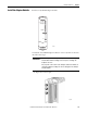
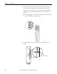
Figure 55 - Module Coding Peg Sockets and Positions
32097-M
Coding Peg Positions
32062-M
32085-M
Coding Peg Socket