
User Manual Owner manual

102 Rockwell Automation Publication 1715-UM001C-EN-P - March 2014
Chapter 2 Installation Instructions
Connect the Adapter to the
Ethernet Network
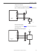
The adapter module supports DLR (Ring) and Star topologies. For more details
on topologies, see System Architecture
on page 16.
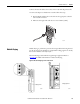
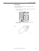
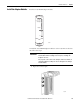
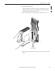
The adapter module has four autosensing 10/100BASE-TX Ethernet ports for
connecting to a local area network through a minimum Cat5e shielded twisted
pair (STP) Ethernet cable. There are two ports for each adapter module.
The adapter module Ethernet ports are on the 1715-A2A adapter base unit and
are identified in this table.
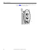
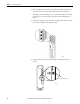
The fixed connectors on the adapter module are female RJ45 modular jacks. Use
a minimum Cat5e shielded twisted pair (STP) cable with male RJ45 modular
jacks for network cabling.
IMPORTANT
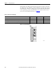
For wiring details, see Tab le 12.
IMPORTANT
The 1715 Redundant I/O System requires the use of a minimum Cat5e shielded
twisted pair (STP) Ethernet cable.
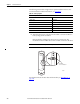
Table 12 - Allocation of 10/100BASE-TX Ports to Adapter Modules
1715-AENTR Adapter Module 10/100BASE-TX Ports
Adapter A A1, A2
Adapter B (where present) B1, B2
IMPORTANT
Most network connections use straight-through cables. Crossover cables are
not needed due to the intelligence or functionality of the switch. If a direct
connection is required from the adapter to the personal computer (for
example, during setup), it can be necessary to use a crossover cable. This
depends on the characteristics of the interface in the personal computer.