
Manual
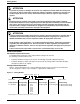
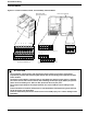
Table Of Contents
- 161 Appx_a.pdf
- New 161_bkcvr.pdf
- 161 Chptr_3.pdf
- Programming Keypad
- Programming Examples
- Initial Power Up
- Scrolling through parameter groups
- Operation of the Drive via the Fixed Keypad
- Note: The factory default settings for the “U” version drive is three wire control (PC03 is set t...
- Note: The direction of rotation is controlled by PF04 - [Start Key Direction]. Refer to page 22 o...
- Activating the Speed Pot on the Keypad
- Parameter A01-[Frequency Command Select] is used to select the source of the frequency command.
- Note: The output frequency of the Bulletin 161 can also be controlled digitally from the keypad b...
- Note: If a digital input is set as 27 (UP) or 28 (DWN), when activated these inputs will also cha...
- Restoring Factory Defaults
- Parameter Descriptions
- 161 Chptr_2.pdf
- 161 Chptr_4.pdf
Getting Started
2
General information
Conventions used in this manual
To help differentiate parameter names and parameter settings from other text
the following conventions will be used:
• Parameter numbers and names are shown in the following way: Pd01 - [Output Frequency]
• Parameter Settings for inputs and outputs are shown with the setting number followed by the alpha
description in {Braces} ex: 18{RS}
Catalog Number Explanation
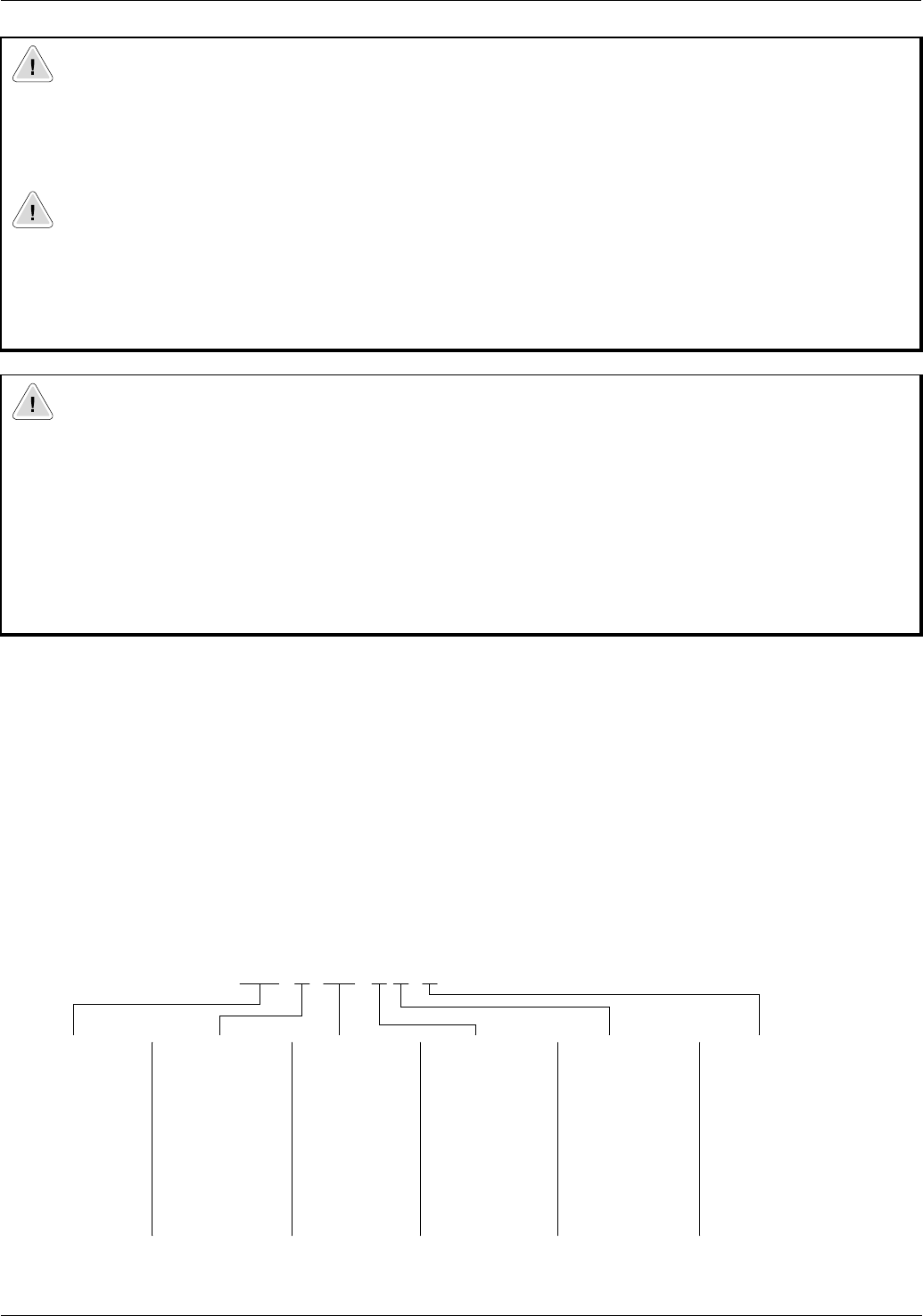
Figure 1.1 below describes the 161 catalog numbering scheme. Please note that not all combinations
can be configured as a Drive, refer to Chapter 5 – Specifications & Dimensions.
Figure 1.1Catalog Number
ATTENTION
• To prevent any injuries or damage, do not touch any components located within the housing with
your hands or with any other objects while input voltage is applied or if the DC-bus capacitors are
not discharged. Do not carry out any work on the wiring or check any signals if input voltage is
applied.
ATTENTION
• Ensure that the input voltage corresponds to the voltage indicated on the product nameplate.
Environmental influences such as high temperatures and high relative humidity are to be avoided as
well as dust, dirt and corrosive gases. The mounting location should be well ventilated and not
exposed to direct sunlight. Install the device upright on a non-flammable, vertical wall. Failure to
observe this precaution could result in damage to the equipment.
ATTENTION
• The drive start/stop and enable control circuitry includes solid-state components. If hazards due to
accidental contact with moving machinery or unintentional flow of liquid, gas or solids exist, an
additional hardwired stop circuit is required to remove AC input power to the drive.
• All the pertinent safety regulations, e.g. accident prevention regulations, professional association
regulations, EN, VDE regulations etc. must be observed. As these regulations are implemented
differently in different countries, the user must observe the regulations that apply for his particular
country.
Failure to observe these precautions could result in severe bodily injury or loss of life.
161S
First Position Second Position Third Position Fourth Position Fifth Position Sixth Position
Bulletin Number Voltage Rating Current Rating Enclosure Type Programmer Default Setting
S = Standard
1
A = 200-240V A 01 N = Open (IP20) P = Fixed Keypad K = 50 Hz default settings
A A01 N P K-
D = 100-120V A 02
A 03
A 04
A 05
A 07
A 10
A 15
U = 60 Hz default settings
1 Ratings through 3 HP (2.2 KW) are rated for single or three phase input