
Manual

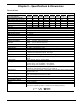
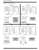
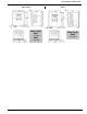
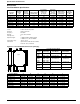
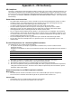


Table Of Contents
- 161 Appx_a.pdf
- New 161_bkcvr.pdf
- 161 Chptr_3.pdf
- Programming Keypad
- Programming Examples
- Initial Power Up
- Scrolling through parameter groups
- Operation of the Drive via the Fixed Keypad
- Note: The factory default settings for the “U” version drive is three wire control (PC03 is set t...
- Note: The direction of rotation is controlled by PF04 - [Start Key Direction]. Refer to page 22 o...
- Activating the Speed Pot on the Keypad
- Parameter A01-[Frequency Command Select] is used to select the source of the frequency command.
- Note: The output frequency of the Bulletin 161 can also be controlled digitally from the keypad b...
- Note: If a digital input is set as 27 (UP) or 28 (DWN), when activated these inputs will also cha...
- Restoring Factory Defaults
- Parameter Descriptions
- 161 Chptr_2.pdf
- 161 Chptr_4.pdf

43
Appendix A – CE Conformity
CE Compliance
This drive is a component intended for implementation in machines or systems for the industrial environment. It is
CE marked for conformity to the Low Voltage (LV) directive 73/23/EEC when installed as described. It also has
been tested to meet the Council Directive 89/336 Electromagnetic Compatibility (EMC). The standards used for
this testing are, LV: EN50178, EN60204-1, EN60950, EMC: EN61800-3 (EN55011, Group 1, Class B (Industrial
Environment)).
General Notes and Instructions
• The motor cable should be kept as short as possible in order to avoid electromagnetic emission as well as
capacitive currents. The cable length increases the capacitive current and electromagnetic emission.
It is recommended that the motor cable length does not exceed 50m.
It is always recommended to install output reactors if the cable length exceeds 50m.
• The filters contain capacitors between the phases and the phases to ground as well as suitable
discharging resistors, but after switching off the line voltage wait a minimum of 60 seconds before
removing protective covers or touching terminals to avoid an electric shock.
• The use of ground fault monitoring devices (RCD’s) is not recommended. If unavoidable, only monitoring
devices which are suited for DC, AC and High Frequency ground currents (type B RCD’s) should be used.
It is recommended to use devices whose responsiveness and time characteristics are adjustable, to avoid
nuisance tripping during power up of the drive.
• The thermal capacity of the line filter is guaranteed up to a maximum motor cable length of 50m.
• The line filters have been developed for use in grounded systems. Use in ungrounded systems is not
recommended.
Essential Requirements for a Conforming EMC Installation
The following items are required for CE conformance.
1. An input filter module (See Chapter 5 Specifications and Dimensions) must be installed to reduce
conducted emissions.
Compliance of the Bulletin 161 drive to the conducted emissions levels with appropriate line filter module is
as follows:
2. Grounding of equipment and cable shields must be solid with low impedance connections.
3. All motor cables must use shielded cable, or be in grounded metal conduit.
4. All control and signal wiring must use shielded cable or be in grounded metal conduit.
5. Ensure that the protective earth ground terminal (PE) of the filter is properly connected with the protective
earth ground terminal of the drive. The filter must be solidly and permanently connected with the ground
potential to avoid electric shock.
General Instructions for an EMC Compliant Installation
Motor Cable
• The cable between the drive and motor must be 4-wire shielded cable (three phases and ground).
• Do not exceed the maximum motor cable length for the specific line filter module used.
Control Cable
• Control wiring must use shielded cable or grounded metal conduit.
• The shield must be connected to PE at both ends of the cable.
PWM Carrier Frequency Motor Cable Length Limit
</= 16kHz 10m Class B
</= 5kHz 20m Class B
</= 16kHz 50m Class A