
Manual

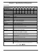
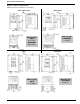
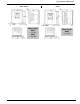
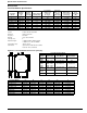


Table Of Contents
- 161 Appx_a.pdf
- New 161_bkcvr.pdf
- 161 Chptr_3.pdf
- Programming Keypad
- Programming Examples
- Initial Power Up
- Scrolling through parameter groups
- Operation of the Drive via the Fixed Keypad
- Note: The factory default settings for the “U” version drive is three wire control (PC03 is set t...
- Note: The direction of rotation is controlled by PF04 - [Start Key Direction]. Refer to page 22 o...
- Activating the Speed Pot on the Keypad
- Parameter A01-[Frequency Command Select] is used to select the source of the frequency command.
- Note: The output frequency of the Bulletin 161 can also be controlled digitally from the keypad b...
- Note: If a digital input is set as 27 (UP) or 28 (DWN), when activated these inputs will also cha...
- Restoring Factory Defaults
- Parameter Descriptions
- 161 Chptr_2.pdf
- 161 Chptr_4.pdf
39
Chapter 5 – Specifications & Dimensions
Technical Data
Series Bulletin 161
Type A01 A02 A03 A04 A05 A07 A10 A15
Drive rating kW (HP)
0.2 (0.3) 0.4 (0.5) .55 (.75) 0.75 (1) 1.1 (1.5) 1.5 (2) 2.2 (3) 3.7 (5)
115V Input rated current (A)
5.5 10.0 N/A 16.0 N/A N/A N/A N/A
230V 1F Input rated current (A)
3.1 5.8 6.7 9.0 11.2 16.0 22.5 N/A
230V 3F Input rated current (A)
1.8 3.4 3.9 5.2 6.5 9.3 13.0 20.0
Output rated current (A)
1.4 2.6 3.0 4.0 5.0 7.1 10.0 15.9
Power Dissipation (W)
17 29 33 41 53 70 101 169
Mass (kg)
See dimension drawings on following page.
Input voltage (V)
200 V -10% to 240 V + 5%, 50/60 Hz +/- 5%; 100V -5% to 120V +5%
Output voltage
3 Φ adjustable from 0 to 230V
Type of protection
IP20
PWM carrier frequency
0.5 - 16 kHz
V/Hz characteristics
Programmable V/Hz ratio, V/Hz control (constant torque, variable torque)
Type of control
Voltage-driven, PWM sine weighted, IGBT-Power module
Output frequency
0.5 - 360 Hz
Accuracy of frequency
command
Digital: +/- 0.01% of max. frequency
Analog: +/- 0.2% of max. frequency
Frequency resolution
Digital: 0.1 Hz, analog: 0.01% of max. frequency
Overload capacity
Software: 150% for 60 s (once in a period of 10 min.), Hardware: 220%
Starting torque
min. 150% at frequencies >3 Hz
DC brake
Starting frequency, braking torque, running times are variable.
Analog inputs
0 -10 V, input impedance 10 kΩ
4 - 20 mA, input impedance 250 Ω PTC input
Digital inputs
5 programmable level triggered inputs, 24V PNP logic, NO or NC contacts
Analog outputs
1 programmable output. 0-10V, 1mA, Accuracy: +/- 5% for frequency, +20% for
current.
Digital outputs
2 open collector outputs. 27VDC, 50mA
Relay output
1 fault indication relay (change-over contact)
Resistive rating: 2.5A at 250VAC – 3A at 30VDC
Inductive rating: 0.2A at 250VAC – .7A at 30VDC
Protection functions
Over-current, over-voltage, under-voltage, electronic motor protection, over-
temperature, ground fault, overload etc. (see Chap.4).
Other functions
15 preset speeds, PID control, unintentional start protection, RS422 serial interface,
skip frequencies etc.
Ambient temperature
-10 - +40 °C (up to +50 °C by removing top cover, reducing carrier frequency to
2kHz, and derating output current by 20%)
Relative humidity
20 - 90% relative humidity, no condensation
Vibration/Shock
Vibration: 0.6G operational / Shock: 10.0G operational
Max. installation altitude
1000 m (3300 ft.) above sea level
Options
Line filter modules
Standards
EN 61800-3 EMC guidelines in connection with optional line filter modules
in line with installation guidelines, EN 50178 Low-Voltage guideline,