
Manual
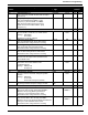
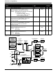
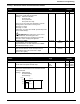
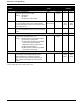
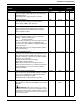
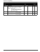
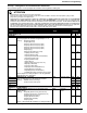
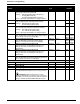
Table Of Contents
- 161 Appx_a.pdf
- New 161_bkcvr.pdf
- 161 Chptr_3.pdf
- Programming Keypad
- Programming Examples
- Initial Power Up
- Scrolling through parameter groups
- Operation of the Drive via the Fixed Keypad
- Note: The factory default settings for the “U” version drive is three wire control (PC03 is set t...
- Note: The direction of rotation is controlled by PF04 - [Start Key Direction]. Refer to page 22 o...
- Activating the Speed Pot on the Keypad
- Parameter A01-[Frequency Command Select] is used to select the source of the frequency command.
- Note: The output frequency of the Bulletin 161 can also be controlled digitally from the keypad b...
- Note: If a digital input is set as 27 (UP) or 28 (DWN), when activated these inputs will also cha...
- Restoring Factory Defaults
- Parameter Descriptions
- 161 Chptr_2.pdf
- 161 Chptr_4.pdf
Parameters & Programming
34
1
U = 60 Hz default settings, K = 50 Hz default settings. Settable using
P
b85 – [Factory Default Select]
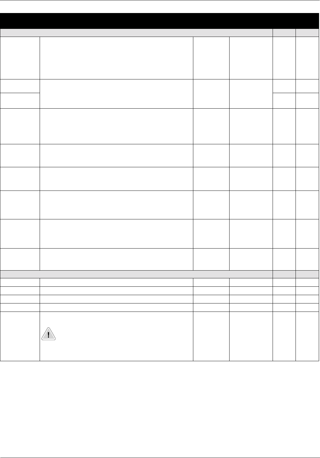
Parameter
Number
Parameter Name / Description Min./Max
Range
Units Factory
Defaults
Outputs 11, 12, FM, AL0-AI1
U
1
K
1
C23 [Output FM Select]
Sets the operation of the output FM.
Settings: 00={A-F} (Analog Output Frequency)
01={A} (Motor Current)
02={D-F} (Digital Output Frequency)
Refer to control inputs table in Chapter 2 for setting descriptions
.
00/02 Numeric Value 00 00
C31 [Digital Output 11-12 Logic]
Sets the digital outputs to be NO or NC contacts.
Settings: 00=NO contact (Active high)
01=NC contact (Active open)
00/01 Numeric Value 00 00
C32 00 00
C33 [Fault Relay AL1 Logic]
Sets the fault relay to be either NO or NC contacts.
Settings: 00 = NO contact (active high)
01 = NC contact (active open)
Refer to control inputs table in Chapter 2 for setting descriptions
.
00/01 Numeric Value 01 01
C41 [Overload Alarm Threshold]
Sets the allowable overload level before digital outputs
11-12 change state when set to 03 {0L}.
0/200% of
drive rating
0.01 A 100%
of drive
rating
100%
of drive
rating
C41 [Overload Alarm Threshold]
Sets the allowable overload level before digital
outputs 11-12 change state when set to 03 {0L}.
0/200% of
drive rating
0.01 A 100%
of drive
rating
100%
of drive
rating
C42 [Above Frequency Accel Threshold]
Sets the frequency at which digital outputs 11-12
change state when set to 02 {FA2} if the drive is
accelerating.
0.0/360.0 0.1 Hz 0.0 0.0
C43 [Above Frequency Decel Threshold]
Sets the frequency at which digital outputs 11-12
change state when set to 02 {FA2} if the drive is
decelerating.
0.0/360.0 0.1 Hz 0.0 0.0
C44 [PID Deviation Threshold]
Sets the allowable PID Loop error before digital outputs
11-12 change state when set to 04 {OD}.
0.0/100% +/- 0.1% +/-3.0 +/-3.0
Communications
U
1
K
1
C70 [Unassigned]
C71 [Unassigned]
C72 [Unassigned]
C79 [Unassigned]
C91 Debug Mode
Used by Rockwell Automation field service personnel.
ATTENTION If PC91-[Debug Mode] is set to 01
parameters
P
C92-
P
C95 are enabled. Changing parameters
PC92-PC95 can lead to personal injury, death, or equipment
damage. DO NOT CHANGE PARAMETERS
P
C91-
P
C95.