
Manual
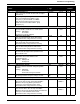
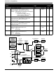
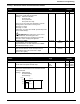
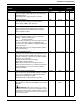
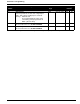
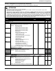
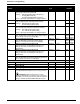
Table Of Contents
- 161 Appx_a.pdf
- New 161_bkcvr.pdf
- 161 Chptr_3.pdf
- Programming Keypad
- Programming Examples
- Initial Power Up
- Scrolling through parameter groups
- Operation of the Drive via the Fixed Keypad
- Note: The factory default settings for the “U” version drive is three wire control (PC03 is set t...
- Note: The direction of rotation is controlled by PF04 - [Start Key Direction]. Refer to page 22 o...
- Activating the Speed Pot on the Keypad
- Parameter A01-[Frequency Command Select] is used to select the source of the frequency command.
- Note: The output frequency of the Bulletin 161 can also be controlled digitally from the keypad b...
- Note: If a digital input is set as 27 (UP) or 28 (DWN), when activated these inputs will also cha...
- Restoring Factory Defaults
- Parameter Descriptions
- 161 Chptr_2.pdf
- 161 Chptr_4.pdf
33
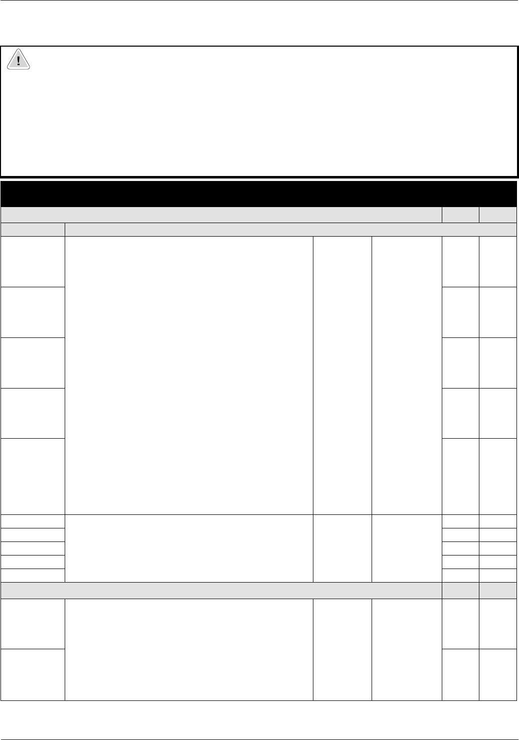
Parameters & Programming
C Group – Intelligent I/O and Communication Parameters
This parameter group is used to program the functions of the digital and analog I/O.
1
U = 60 Hz default settings, K = 50 Hz default settings. Settable using Pb85 – [Factory Default Select]
ATTENTION
• All digital inputs respond to level sensitive commands.
• Inputs do not require a voltage transition (cycle) after a fault condition is cleared, after input power cycling or after
programming the logic of the digital input.
• All digital inputs can be programmed as NO or NC. HOWEVER, The START COMMAND SHOULD BE SET AS NO (ACTIVE
HIGH) AND THE STOP COMMAND SHOULD BE SET AS NC (ACTIVE OPEN). If set opposite of this, an inadvertent start
or failure to stop could occur should a discrete connection be lost or control wire come loose. IF THE USER CHOOSES TO
DISREGARD THIS SAFETY PRACTICE – THE RISK ASSUMED BY THE USER CAN BE REDUCED BY ASSURING THAT
OTHER SAFEGUARDS ARE USED TO INSURE PROPER START AND STOP OPERATION. Depending on the application:
This may include appropriate emergency stops, redundant wiring, electronic guards and/or mechanical guards.
Failure to observe this precaution could result in severe bodily injury or loss of life.
Parameter
Number
Parameter Name / Description Min./Max
Range
Units Factory
Defaults
Digital Inputs 1 – 5 U
1
K
1
Parameter
C01 [Digital Inputs 1-5]
Used to program the function of digital inputs 1 – 5.
Settings: 00={FW} (Forward)
01={RV} (Reverse)
02={CF1} (Preset Frequency Input)
03={CF2} (Preset Frequency Input)
04={CF3} (Preset Frequency Input)
05={CF4} (Preset Frequency Input)
06={JG} (Jog)
09={2CH} (Accel/Decel 2 Select)
11={FRS} (Coast to Stop)
12={EXT} (External Trip)
13={USP} (Unintentional Start Protection)
15={SFT} (Program Lock)
16={AT} (4-20mA Select)
18={RS} (Reset)
19={PTC} (PTC Input)
input C05 only
20={STA} (3 Wire Run)
21={STP} (3 Wire Stop)
22={F/R} (3 Wire Forward/Reverse)
27={UP} (Remote Control Up)
28={DWN} (Remote Control Down)
31={OPE} (Run/Stop Command Source Select)
Refer to Chapter 2 for setting descriptions of the “Programmable
Digital Input Functions” listed above.
00/31 Numeric Value 22 00
C02 20 01
C03 21 02
C04 18 03
C05 13 13
C11 [Digital Inputs 1-5 Logic]
Sets the digital inputs to be NO or NC contacts
Settings: 00=NO contact (active high)
01=NC contact (active open)
00/01 Numeric Value 00 00
C12 00 00
C13 01 00
C14 00 00
C15 01 01
Outputs 11, 12, FM, AL0-AL1 U
1
K
1
C21 [Digital Outputs 11-12] Sets the operation of the
digital outputs
Settings: 00={RUN} (Motor running above 0.5 Hz)
01={FA1} (At frequency and above 0.5 Hz)
02={FA2} (Above frequency)
03={OL} (Overload alarm)
04={OD} (PID deviation)
05={AL} (Fault)
Refer to control terminal table in Chapter 2 for setting descriptions
.
00/05 Numeric
Value
01 01
C22 00 00