
Manual
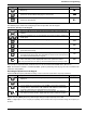
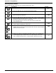
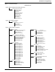
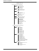
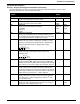
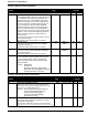
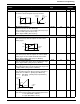
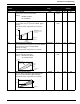
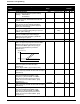
Table Of Contents
- 161 Appx_a.pdf
- New 161_bkcvr.pdf
- 161 Chptr_3.pdf
- Programming Keypad
- Programming Examples
- Initial Power Up
- Scrolling through parameter groups
- Operation of the Drive via the Fixed Keypad
- Note: The factory default settings for the “U” version drive is three wire control (PC03 is set t...
- Note: The direction of rotation is controlled by PF04 - [Start Key Direction]. Refer to page 22 o...
- Activating the Speed Pot on the Keypad
- Parameter A01-[Frequency Command Select] is used to select the source of the frequency command.
- Note: The output frequency of the Bulletin 161 can also be controlled digitally from the keypad b...
- Note: If a digital input is set as 27 (UP) or 28 (DWN), when activated these inputs will also cha...
- Restoring Factory Defaults
- Parameter Descriptions
- 161 Chptr_2.pdf
- 161 Chptr_4.pdf
23
Parameters & Programming
A03 [Base Frequency]
Set value to rated nameplate frequency of motor
50/360 1 Hz 60 50
A04 [Maximum Frequency]
Highest frequency the drive will output.
Note: If a maximum frequency less than PA03 – [Base Frequency] is
needed, use PA61 – [Upper Frequency Limit].
Refer to diagram in PA03 – [Base Frequency].
50/360 1Hz 60 50
Analog input reference adjustment U
1
K
1
A11 [Analog Frequency Minimum]
Sets the frequency that corresponds to a 0V or 4mA
analog signal.
0.0/360.0 0.1 Hz 0.0 0.0
A12 [Analog Frequency Maximum]
Sets the frequency that corresponds to a 10V or 20mA
analog signal. A value of 0.0 will disable this function.
Refer to diagram in PA11 – [Analog Frequency Minimum].
0.0/360.0 0.1 Hz 0.0 0.0
A13 [Analog Input Minimum]
Sets the starting point (offset) for the analog input range.
Refer to diagram in PA11 - [Analog Frequency Minimum]
0/99 1% 0 0
A14 [Analog Input Maximum]
The ending point (offset) for the analog input range.
Refer
to diagram in PA11 - [Analog Frequency Minimum].
0/100 1% 100 100
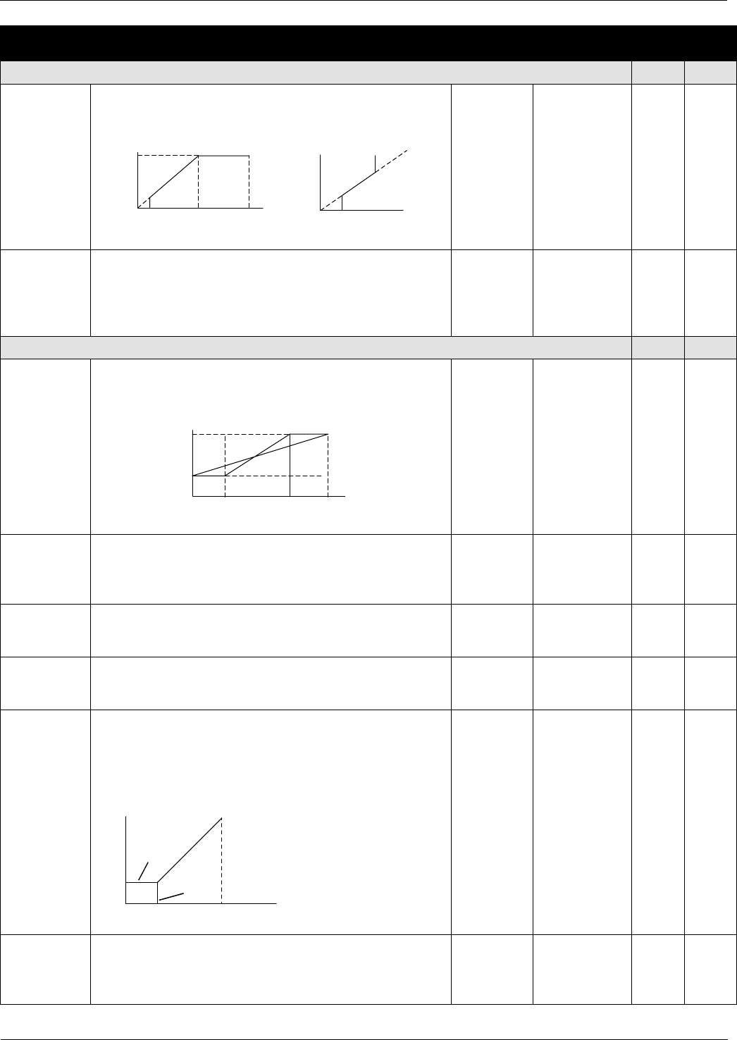
A15 [Analog Start Select]
Sets the output frequency when frequency reference is
below value set in PA13 – [Analog Input Minimum].
Settings: 00 = PA11 - [Analog Frequency Minimum]
01 = 0 Hz
00/01 Numeric Value 01 01
A16 [Analog Filter Select]
Sets the level of the Analog input smoothing filter where:
1 = low. (Bandwidth = 200 Hz)
8 = high. (Bandwidth = 25 Hz)
1/8 Numeric Value 8 8
Parameter
Number
Parameter Name / Description Min./Max
Range
Units Factory
Defaults
Basic Functions U
1
K
1
Voltage
100%
0
Start
Frequency
b82
Base
Frequency
A03
Maximum
Frequency
Frequency
Frequency
Frequency Limit
A61
Minimum
Frequency
A62
Hz
Command
Upper
A04
A12
A11
0V 10VA13 A14
4mA 20mA
% Input
Scale
Frequency
A15=00
A15=01
A12
A11
0V 10VA13 A14
4mA 20mA
% Input
Scale