
Manual
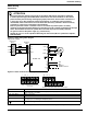
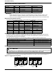
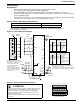
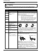
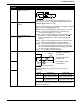
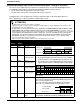
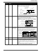
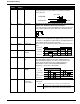
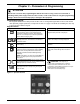
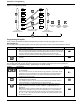
Table Of Contents
- 161 Appx_a.pdf
- New 161_bkcvr.pdf
- 161 Chptr_3.pdf
- Programming Keypad
- Programming Examples
- Initial Power Up
- Scrolling through parameter groups
- Operation of the Drive via the Fixed Keypad
- Note: The factory default settings for the “U” version drive is three wire control (PC03 is set t...
- Note: The direction of rotation is controlled by PF04 - [Start Key Direction]. Refer to page 22 o...
- Activating the Speed Pot on the Keypad
- Parameter A01-[Frequency Command Select] is used to select the source of the frequency command.
- Note: The output frequency of the Bulletin 161 can also be controlled digitally from the keypad b...
- Note: If a digital input is set as 27 (UP) or 28 (DWN), when activated these inputs will also cha...
- Restoring Factory Defaults
- Parameter Descriptions
- 161 Chptr_2.pdf
- 161 Chptr_4.pdf
Parameters & Programming
16
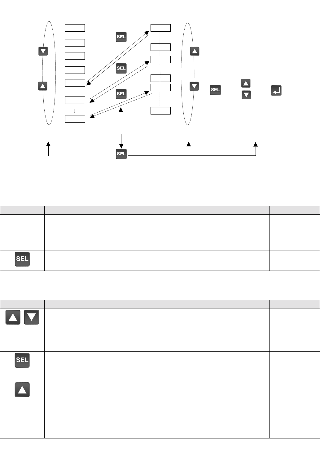
Figure 3.2 Programming Guide
Programming Examples
In this section you will find four different programming examples to help you program the 161 drive.
Initial Power Up
This example shows you how to proceed from the power up parameter value to the actual parameter number.
Scrolling through parameter groups
This example will show you how to check a parameter value without changing the value of the parameter.
For this example, the operation of PC21 - [Digital Output 11] will be verified.
Action Description Display
1. Apply power to the Drive
Note: If you were viewing a display parameter when power was last removed from the
drive, the same display parameter value will reappear when the drive is re-powered. If
you were viewing any other parameter value when power was removed, the
parameter group or parameter number will appear when the drive is re-powered.
0.0
0.00.0
0.0
2. Press the SELect Key to switch from the parameter value to the parameter
number.
d 01
d 01d 01
d 01
Action Description Display
3. Press the Up/Down keys to scroll through the parameter groups, stopping
at the C group.
Note: You must scroll thru all of the d and F group parameters, but the A, b, and C
parameters are grouped and the group must be SELected to view the parameters
within that specified group. Figure 3.3 contains a hierarchy which details which
parameters are in each group.
C - -
C - -C - -
C - -
4. Press the SELect Key to enter into the C group. PC01 - [Digital Input 1]
should appear on the display.
Note: When parameter groups are entered, the number of the parameter that was
being viewed when you last exited the group will be displayed.
C 01
C 01C 01
C 01
5. Press the Up Key to scroll through the parameters contained within the
group, continue pressing the Up Key until PC21 - [Digital Output 11] is
displayed.
Note: When viewing parameters within the A, b and C groups the parameters will
wrap from A01 through C91 by pressing the Up/Down Keys. To view parameters
within the d and F groups the SELect Key must be pressed until the display shows
A - -, b - - or C- -. Once the group letter is displayed, the Up/Down Key will scroll to
the d and F parameters.
C 21
C 21C 21
C 21
d01
d09
F01
F04
A ..
C ..
B ..
A01
A98
C01
C91
b01
b89
Scroll Thru
Parameter Groups
Press SEL to enter
parameter group.
Scroll Thru
Parameter Numbers
View
Parameter
Value
Parameter
Value
Change
Save
Entered
Parameter
Value