
Manual
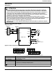
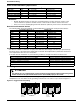
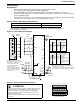
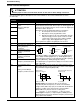
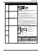
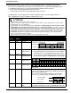
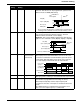
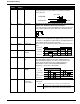
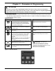
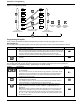
Table Of Contents
- 161 Appx_a.pdf
- New 161_bkcvr.pdf
- 161 Chptr_3.pdf
- Programming Keypad
- Programming Examples
- Initial Power Up
- Scrolling through parameter groups
- Operation of the Drive via the Fixed Keypad
- Note: The factory default settings for the “U” version drive is three wire control (PC03 is set t...
- Note: The direction of rotation is controlled by PF04 - [Start Key Direction]. Refer to page 22 o...
- Activating the Speed Pot on the Keypad
- Parameter A01-[Frequency Command Select] is used to select the source of the frequency command.
- Note: The output frequency of the Bulletin 161 can also be controlled digitally from the keypad b...
- Note: If a digital input is set as 27 (UP) or 28 (DWN), when activated these inputs will also cha...
- Restoring Factory Defaults
- Parameter Descriptions
- 161 Chptr_2.pdf
- 161 Chptr_4.pdf
13
Installation & Wiring
11 {FRS} Coast to Stop The motor voltage will be switched off immediately and the motor
will coast. This function can be programmed to operate in two
different modes via Pb88-[FRS Select].
Note: The drive will start when 11 {FRS} input is removed without
reissuing a start command even if in 3 wire (momentary) control.
12 {EXT} External Fault When this input is active, an E12 fault indication will be issued
(e.g. an input received from thermal contacts). The fault
indication will be cleared with a reset 18{RS}.
Important: After a reset 18{RS} command, the drive will start
again if a start command is active (00{FW}, 01{RV},or 20{STA}).
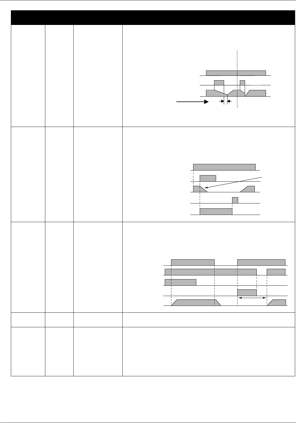
13 {USP} Unintentional
Start Protection
on Power Up
This function is designed to guard against unintended starting
when input power is removed and then restored. In this case,
if a start/run command is issued immediately upon/after power
is restored an E13 fault will be issued. A new start command
or a reset 18{RS} command will clear the fault indication.
15 {SFT} Program Lock Protects stored parameter values from being overwritten. See
Pb31-[Program Lock Select] for the 4 different levels of protection.
16 {AT} 4-20mA Select Activates input terminal OI for use as a 4-20mA input. If no
input terminal is programmed for this setting, the factory
default input is O (0-10V) and the output frequency will
correspond to the value of the inputs to the O and/or OI control
inputs.
Note: PA01-[Frequency Command Select] determines from
what source the output frequency is commanded.
C01 - C05
Setting
Alpha
Setting
Function Description
0
H
z
s
t
a
r
t
s
y
n
c
h
r
o
n
i
z
a
t
i
o
n
o
f
m
o
t
o
r
s
p
e
e
d
Run (NO)
Input 11 {FRS} (NO)
Motor speed
Waiting time
Run (NO)
Input 12 {EXT} (NO)
Motor Speed
Motor will
Coast
Input 18 {RS} (NO)
Fault relay (ALO-AI2) (NO)
Power Supply
13 {USP}(N.C.)
Motor Speed
Min. 3 Sec
Fault relay (N.O.)
00{FW} or
01 {RV} (N.O.)