
Manual
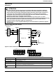
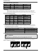
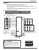
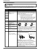
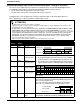
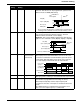
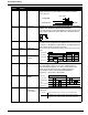
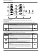
Table Of Contents
- 161 Appx_a.pdf
- New 161_bkcvr.pdf
- 161 Chptr_3.pdf
- Programming Keypad
- Programming Examples
- Initial Power Up
- Scrolling through parameter groups
- Operation of the Drive via the Fixed Keypad
- Note: The factory default settings for the “U” version drive is three wire control (PC03 is set t...
- Note: The direction of rotation is controlled by PF04 - [Start Key Direction]. Refer to page 22 o...
- Activating the Speed Pot on the Keypad
- Parameter A01-[Frequency Command Select] is used to select the source of the frequency command.
- Note: The output frequency of the Bulletin 161 can also be controlled digitally from the keypad b...
- Note: If a digital input is set as 27 (UP) or 28 (DWN), when activated these inputs will also cha...
- Restoring Factory Defaults
- Parameter Descriptions
- 161 Chptr_2.pdf
- 161 Chptr_4.pdf
Installation & Wiring
12
Programmable Digital Input (Control terminal block inputs 1 through 5) Functions
The function of the digital inputs 1 through 5 are programmed via the corresponding PC01 [Digital Input 1]
through PC05 - [Digital Input 5]. The following programming guidelines must be followed:
• No two inputs can be programmed for the same function.
• The PTC input (setting 19) is only programmable on input terminal 5.
The digital inputs can be programmed to respond to NO (Active High) or NC (Active Open) inputs via
PC11 - [Digital Input 1 Logic] through PC15 - [Digital Input 5 Logic].
ATTENTION
• All digital inputs respond to level sensitive commands.
• Inputs do not require a voltage transition (cycle) after a fault condition is cleared, after input power cycling or after
programming the logic of the digital input.
• All digital inputs can be programmed as NO or NC. HOWEVER, THE START COMMAND SHOULD BE SET AS NO
(ACTIVE HIGH) AND THE STOP COMMAND SHOULD BE SET AS NC (ACTIVE OPEN). If set opposite of this, an
inadvertent start or failure to stop could occur should a discrete connection be lost or control wire come loose. IF THE
USER CHOOSES TO DISREGARD THIS SAFETY PRACTICE – THE RISK ASSUMED BY THE USER CAN BE
REDUCED BY ASSURING THAT OTHER SAFEGUARDS ARE USED TO INSURE PROPER START AND STOP
OPERATION. Depending on the application: This may include appropriate emergency stops, redundant wiring,
electronic guards and/or mechanical guards.
Failure to observe this precaution could result in severe bodily injury or loss of life.
C01 - C05
Setting
Alpha
Setting
Function Description
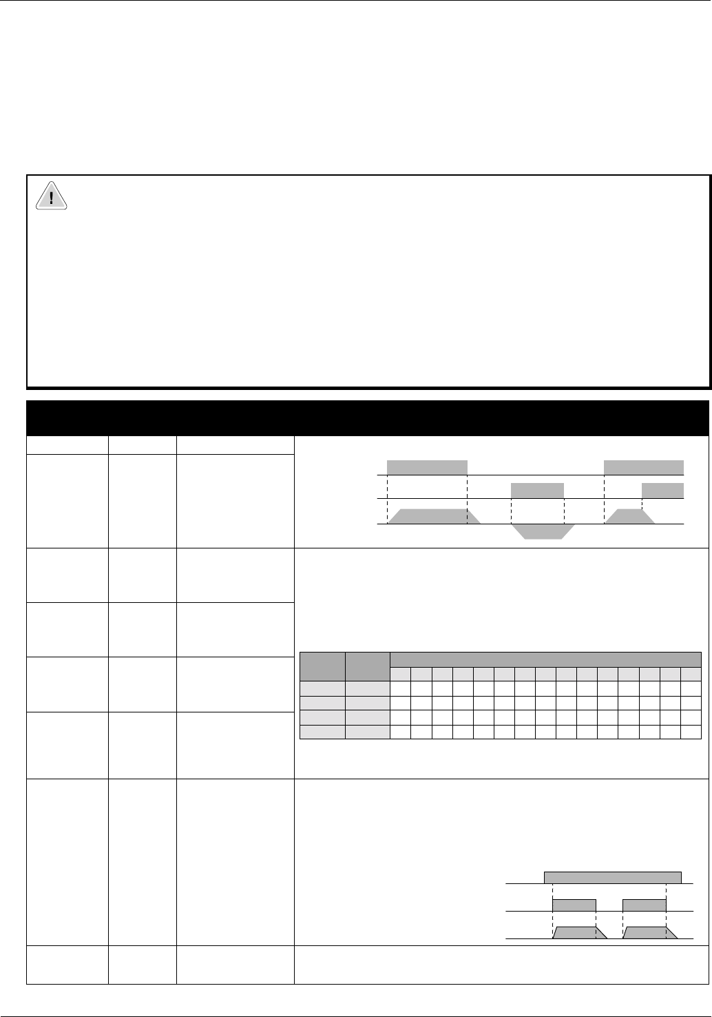
00 {FW} Forward 2-Wire (maintained) Run Forward/Run Reverse settings.
01 {RV} Reverse
02 {CF1} Preset
frequency input
The preset frequencies may be programmed in two ways:
1. By programming desired preset frequency values via PA21-
[Preset Frequency 1] through PA35-[Preset Frequency 15].
2. By selecting the corresponding digital input setting and enter-
ing the desired frequency via PF01-[Frequency Command].
Note: If any preset frequency input is active, all other frequency commands
will be ignored.
03 {CF2} Preset
frequency input
04 {CF3} Preset
frequency input
05 {CF4} Preset
frequency input
06 {JG} Jog When this input is active, the 00{FW} or 01{RV} inputs will
respond to the frequency programmed via PA38-[Jog Frequency].
The accel ramp is NOT active.
The stop command is determined by PA39-[Jog Stop Mode].
Note: The Jog command will not work with 3-wire control.
09 {2CH}
2
nd
Accel/Decel
ramp
2
nd
Accel/Decel ramp times are activated via this input and
programmed via PA92-[Accel Time 2] and PA93-[Decel Time 2].
00{FW}(N.O.)
01{RV}(N.O.)
Motor Speed
Setting Input
Preset Speed
1 2 3 4 5 6 7 8 9 10 11 12 13 14 15
02 CF1ONONONONONONONON
03 CF2 ONON ONON ONON ONON
04 CF3 ONONONON ONONONON
05 CF4 ONONONONONONONON
Input 06 {JG} (NO)
Run Cmd (NO)
Motor Speed