
Manual
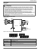
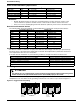
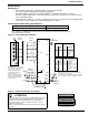
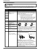
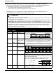
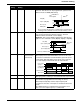
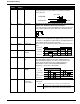
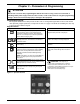
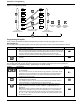
Table Of Contents
- 161 Appx_a.pdf
- New 161_bkcvr.pdf
- 161 Chptr_3.pdf
- Programming Keypad
- Programming Examples
- Initial Power Up
- Scrolling through parameter groups
- Operation of the Drive via the Fixed Keypad
- Note: The factory default settings for the “U” version drive is three wire control (PC03 is set t...
- Note: The direction of rotation is controlled by PF04 - [Start Key Direction]. Refer to page 22 o...
- Activating the Speed Pot on the Keypad
- Parameter A01-[Frequency Command Select] is used to select the source of the frequency command.
- Note: The output frequency of the Bulletin 161 can also be controlled digitally from the keypad b...
- Note: If a digital input is set as 27 (UP) or 28 (DWN), when activated these inputs will also cha...
- Restoring Factory Defaults
- Parameter Descriptions
- 161 Chptr_2.pdf
- 161 Chptr_4.pdf
Installation & Wiring
10
Control Terminal Descriptions
The following table gives a description of each of the terminals on the control terminal block as well as
the fault relay:
ATTENTION
• DO NOT jumper or short circuit terminals H and L or P24 and L or drive damage could occur.
Control
Terminal
Function Description
P24 24 V DC 24 V potential for digital inputs 1-5 max. load 30mA
1 Programmable Digital
Inputs.
26V max, 5KΩ input
impedance.
Digital inputs 1 – 5 are fully programmable level triggered inputs
via parameters C01 thru C05. These inputs are level triggered. An
overview of the possible functions can be found in the digital input
description table in Chapter 2.
The inputs are fully programmable with these exceptions:
1. No two inputs can have the same function
2. Only input 5 can be programmed as PTC.
3. With the exception of the reset setting which must be
NO (active high), all of the inputs can be set as NO
(active high) or NC (active open) via PC11-[Digital
Input 1 Logic] - PC15-[Digital Input 5 Logic].
Note: A signal must be applied to the digital inputs for at least 12 ms
2
3
4
5
L 0 V 0 V potential for output FM
H 10 V Reference Voltage for
Analog Frequency
Command
Input OI for 4-20mA is activated when one of the digital inputs is
set to 16{AT} via PC01-[Digital Input 1] – PC05-[Digital Input 5]
The analog input reference can be adjusted using PA11-[Analog
Frequency Minimum] – PA16-[Analog Filter Select].
If no digital input is programmed as 16{AT}, the set values are the
sum of O and OI.
O Voltage Analog Input
Frequency Command
(0-10V)
OI Current Analog Input
Frequency Command
(4-20 mA)
L 0 V Reference Potential for
Frequency Command Inputs
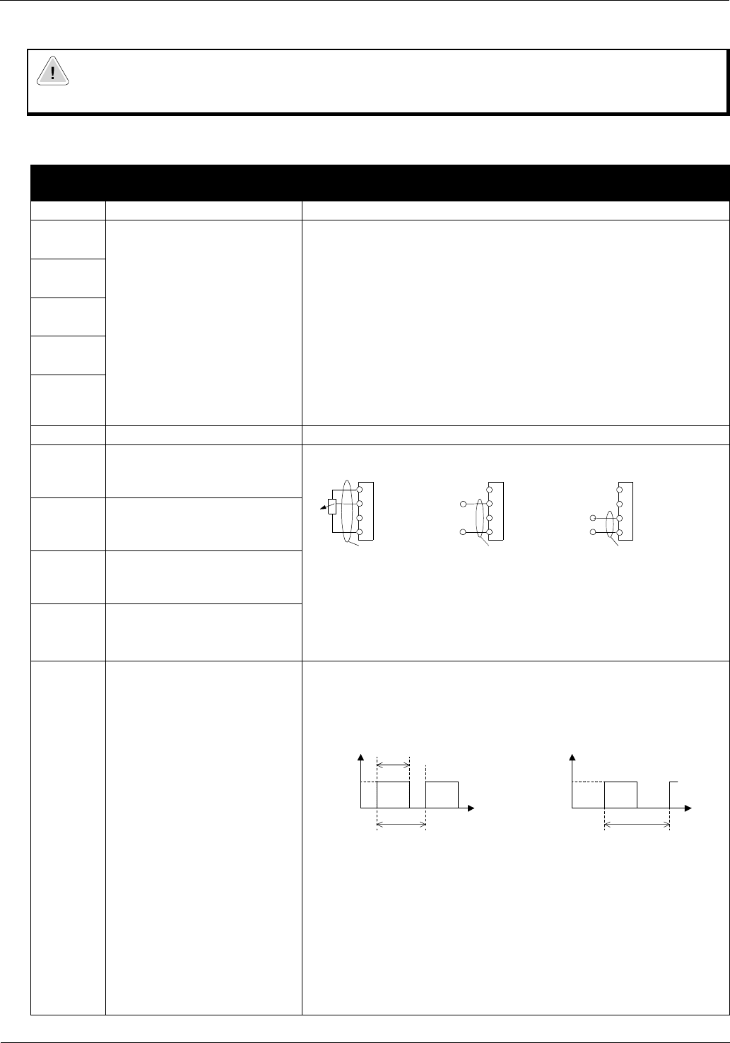
FM Programmable Analog
Output
Analog or Pulse Output
Frequency or Motor Current
This output can be used to monitor the output frequency of the
drive (either Analog or Pulse) or the motor current. This output is
programmable using PC23-[Output FM].
Analog Signal: The relation t/T (duty cycle) changes
proportionally with the frequency or current. The maximum
voltage of 10V (100% duty cycle) is reached when the maximum
frequency or 200% of the rated current is reached. Pb81 -
[Output FM Factor] may be used as a scaling factor.
Accuracy: +/- 5% for frequency , +/- 20% for current
Pulse Signal: Frequency = output frequency x Pb86-[Process
Display Scale Factor], but the maximum frequency is 3.6 kHz (ex.
Freq = 60Hz x 60 = 3.6kHz).
Potentiometer
1 to 2 kOhm
4-19.6 mA
nominal 0-20 mA
0-9.6 V
nominal 0-10 V
Input impedance
10 kOhm
Input impedance
250 Ohm
H
O
OI
L
H
O
OI
L
H
O
OI
L
+
-
+
PE PE
PE
-
t
T
T
s
s
10 V
10 V
Analog Signal
Frequency or Current
Pulse Signal (50% duty cycle)
Frequency only
T=4ms (constant) T = (Variable)