
Manual
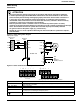
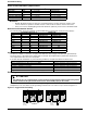
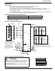
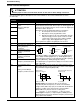
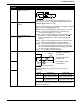
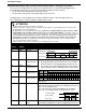
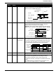
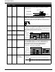
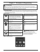
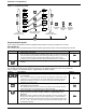
Table Of Contents
- 161 Appx_a.pdf
- New 161_bkcvr.pdf
- 161 Chptr_3.pdf
- Programming Keypad
- Programming Examples
- Initial Power Up
- Scrolling through parameter groups
- Operation of the Drive via the Fixed Keypad
- Note: The factory default settings for the “U” version drive is three wire control (PC03 is set t...
- Note: The direction of rotation is controlled by PF04 - [Start Key Direction]. Refer to page 22 o...
- Activating the Speed Pot on the Keypad
- Parameter A01-[Frequency Command Select] is used to select the source of the frequency command.
- Note: The output frequency of the Bulletin 161 can also be controlled digitally from the keypad b...
- Note: If a digital input is set as 27 (UP) or 28 (DWN), when activated these inputs will also cha...
- Restoring Factory Defaults
- Parameter Descriptions
- 161 Chptr_2.pdf
- 161 Chptr_4.pdf
9
Installation & Wiring
Control Wiring
Requirements
• Run all signal wiring in either a shielded cable or separate metal conduit.
• Do not exceed control wiring length of 20 meters (65.6 feet).
• Use Belden 8760 (or equivalent) –18 AWG (0.750mm
2
), twisted pair, shielded or 3 conductor.
• Avoid crossing the power lines or motor lines with the control wires. If they must cross, ensure that they
cross at right (90
o
) angles.
• If using transistor outputs 11 or 12, with an inductive load such as a relay, install a recovery diode parallel
to the relay as shown in Figure 2.6, to prevent damage to the output.
Control Terminal Block Wiring Specifications
Note: 0.75mm
2
(18 AWG) wire must be used for the alarm relay. Torque the mounting screw
to: 0.5-0.6 Nm (4.4-5.3 in lb).
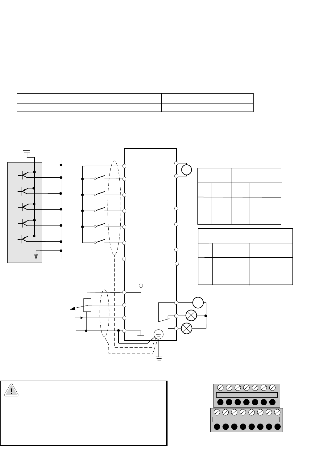
Figure 2.6 Control Wiring Block Diagram
Figure 2.7 Control terminal block descriptions
Max/Min wire size mm
2
(AWG) Max/Min Torque Nm (in lb)
0.750 – 0.14 (18-28) 0.25 - 0.2 (2.21 – 1.77)
ATTENTION
A hazard of electrical shock, death or equipment damage exists.
Control terminals are isolated but not tied to earth ground. If
terminal (L) on the control terminal block is not grounded,
exposed conductors, shields or metal conductors can be at
hazardous voltage levels.
Failure to observe this precaution could result in severe injury or
loss of life.
0-10V
1-2k Ohm
Pot.
4-20mA
Frequency
Reference
10V
P24
1
2
3
4
5
L
H
O
OI
L
Internal
Power
P24
1
24V
2
3
4
5
L
External
Power
I
MPORTANT: Only one frequency
s
ource may be connected at a time.
I
f more than one reference is
c
onnected at the same time,
a
n undetermined frequency
r
eference will result.
T
o improve noise immunity, the
c
ommon (terminal L) must be
c
onnected to ground terminal/
protective earth.
0-10V
PWM OutPut
230V AC
Fault Relay
FM
L
AL0
AL1
AL2
V
~
11
12
CM2
CM2
See Note 2
Parm
C01
C02
C03
C04
C05
Input
Terminal
1
2
3
4
5
Factory Default
Setting & Description
"U"
Default
22
20
21
18
13
1
"U" Default
Description
3 wire fwd/rev
3 wire run
3 wire stop
reset
USP
Parm
C01
C02
C03
C04
C05
Input
Terminal
1
2
3
4
5
Factory Default
Setting & Description
"K"
Default
0
1
2
3
13
"K" Default
Description
Run fwd
Run rev
Preset input 1 (CF1)
Preset input 2 (CF2)
USP
Notes:
1. Parameter C13 is NC. This input must be active
(jumpered) for the drive to run. See following pages
for description of these settings.
2. A contact closure on terminals 3 and P24 is required
for the controller to respond to a Start/Run command.
2
L
HO0ILFM
Control Terminal Block
CM2 12 11
54321P24