
Manual
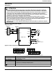
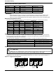
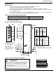
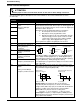
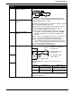
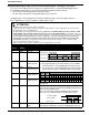
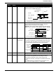
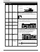
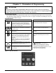
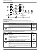
Table Of Contents
- 161 Appx_a.pdf
- New 161_bkcvr.pdf
- 161 Chptr_3.pdf
- Programming Keypad
- Programming Examples
- Initial Power Up
- Scrolling through parameter groups
- Operation of the Drive via the Fixed Keypad
- Note: The factory default settings for the “U” version drive is three wire control (PC03 is set t...
- Note: The direction of rotation is controlled by PF04 - [Start Key Direction]. Refer to page 22 o...
- Activating the Speed Pot on the Keypad
- Parameter A01-[Frequency Command Select] is used to select the source of the frequency command.
- Note: The output frequency of the Bulletin 161 can also be controlled digitally from the keypad b...
- Note: If a digital input is set as 27 (UP) or 28 (DWN), when activated these inputs will also cha...
- Restoring Factory Defaults
- Parameter Descriptions
- 161 Chptr_2.pdf
- 161 Chptr_4.pdf
Installation & Wiring
8
Power Terminal Block Wiring Specifications
Power Terminal Connection
IMPORTANT:
• Bulletin 161 Drives feature an electronic overload protection to monitor the motor current. In the
case of multi-motor operation, thermal contacts or PTC resistors must be used for each motor.
• In the case of motor lead lengths greater than 50 meters (165 feet), motor reactors should be used.
Branch Circuit Protection Devices
The following table shows the minimum recommended values for the branch circuit protection devices:
Input Power Conditioning
The drive is suitable for connection to input power within the rated voltage of the drive (see specifications).
The power factor of the input power supply must not exceed .99. Compensation systems must ensure that
over compensation does not occur at any time.
If the drive must be installed in any of the following conditions, an Input Line Reactor must be used:
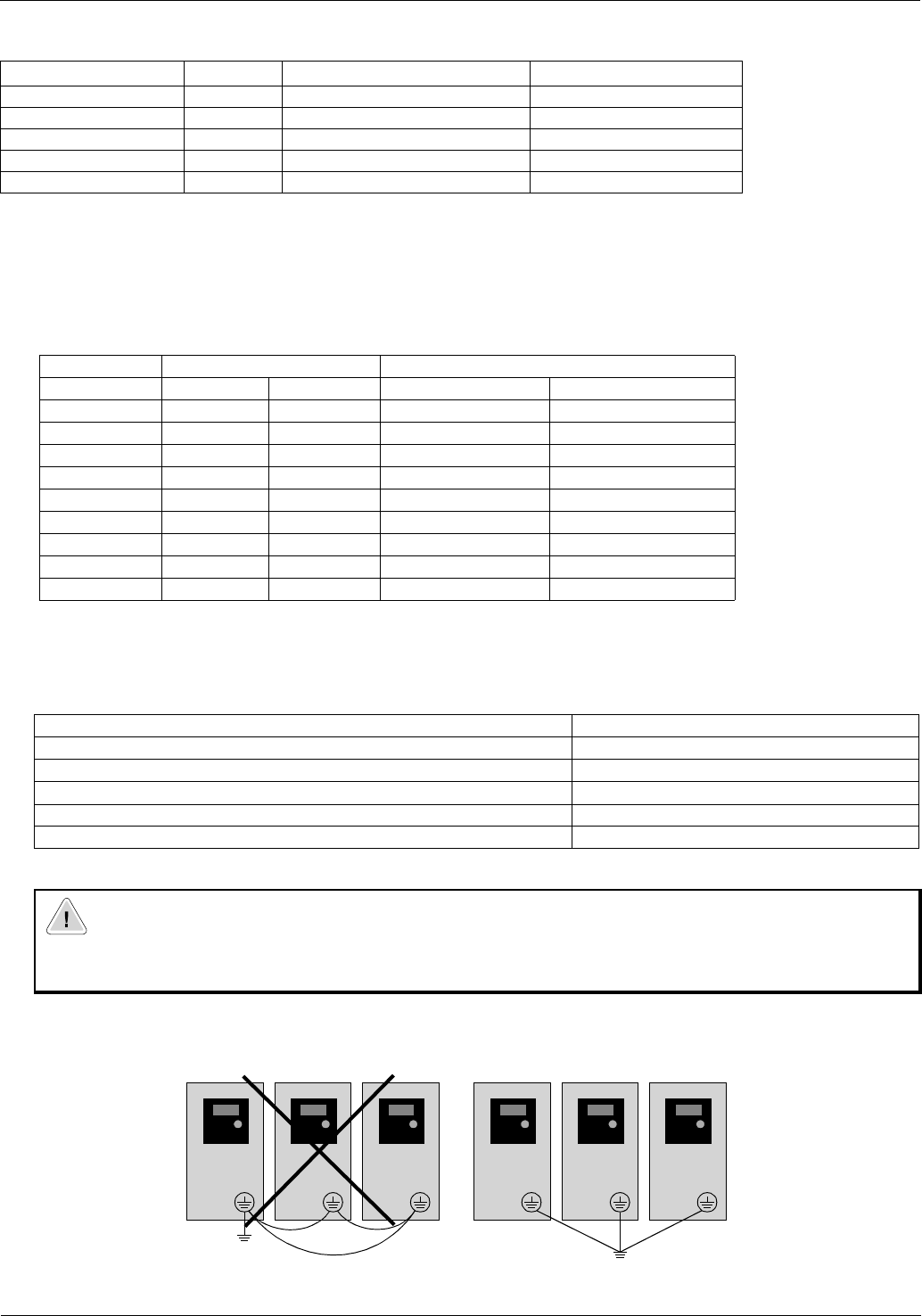
Grounding
Ground the drive. Be sure to separate the drive’s grounding pole from those of other electrical machinery. If
multiple drives are used, make certain grounding connections do not create a loop as shown in Figure 2.5.
Figure 2.5 Suggested 161 Grounding
Model Screw Size Max/Min Wire Size mm
2
(AWG) Max/Min Torque Nm (lbin)
AA01-AA02 M3.5 2.1 – .75 (14-18) 0.9-0.8 (8.0-7.0)
AA03 M3.5 2.1 – 1.3 (14-16) 0.9-0.8 (8.0-7.0)
AA04, DA01 M4 5.3 – 1.3 (10-16) 1.3-1.2 (11.5-10.6)
AA05-AA10, DA02-DA03 M4 5.3 – 2.1 (10-14) 1.3-1.2 (11.5-10.6)
AA15 M4 5.3 – 3.3 (10-12) 1.3-1.2 (11.5-10.6)
Fuse Rating (Class CC, J) Bulletin 140
Model 1 Ph 3 Ph 1 Ph 3 Ph
AA01 10 10 140M-D8N-C10 140M-D8N-B40
AA02-AA03 10 10 140M-D8N-C10 140M-D8N-B63
AA04-AA05 15 15 140M-D8N-C16 140M-D8N-C10
AA07 20 15 140M-D8N-C16 140M-D8N-C16
AA10 30 20 140M-D8N-C25 140M-D8N-C16
AA15 N/A 30 N/A 140M-D8N-C25
DA01 10 N/A 140M-D8N-C10 N/A
DA02 15 N/A 140M-D8N-C10 N/A
DA04 20 N/A 140M-D8N-C16 N/A
Input Power Condition Corrective Action
Line has intermittent noise spikes in excess of 2000V Install 3% impedance Input Line Reactor
If frequent voltage dips occur Install 3% impedance Input Line Reactor
The drive is operated on a generator Install 3% impedance Input Line Reactor
Line has power factor correction capacitors Install 3% impedance Input Line Reactor
Several drives are linked via a short common power supply bus bar. Install 3% impedance Input Line Reactor
ATTENTION
• The Bulletin 161 has a high leakage current and must be permanently (fixed) hard wired to ground.
Failure to observe this precaution could result in severe bodily injury or loss of life.
Bulletin 161
Protective
Earth
Ground
Protective
Earth
Ground
Bulletin 161 Bulletin 161 Bulletin 161 Bulletin 161 Bulletin 161