
Manual
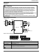
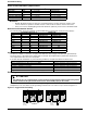
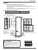
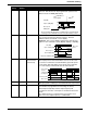
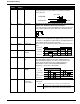
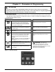
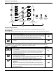
Table Of Contents
- 161 Appx_a.pdf
- New 161_bkcvr.pdf
- 161 Chptr_3.pdf
- Programming Keypad
- Programming Examples
- Initial Power Up
- Scrolling through parameter groups
- Operation of the Drive via the Fixed Keypad
- Note: The factory default settings for the “U” version drive is three wire control (PC03 is set t...
- Note: The direction of rotation is controlled by PF04 - [Start Key Direction]. Refer to page 22 o...
- Activating the Speed Pot on the Keypad
- Parameter A01-[Frequency Command Select] is used to select the source of the frequency command.
- Note: The output frequency of the Bulletin 161 can also be controlled digitally from the keypad b...
- Note: If a digital input is set as 27 (UP) or 28 (DWN), when activated these inputs will also cha...
- Restoring Factory Defaults
- Parameter Descriptions
- 161 Chptr_2.pdf
- 161 Chptr_4.pdf
7
Installation & Wiring
Power Wiring
Precautions:
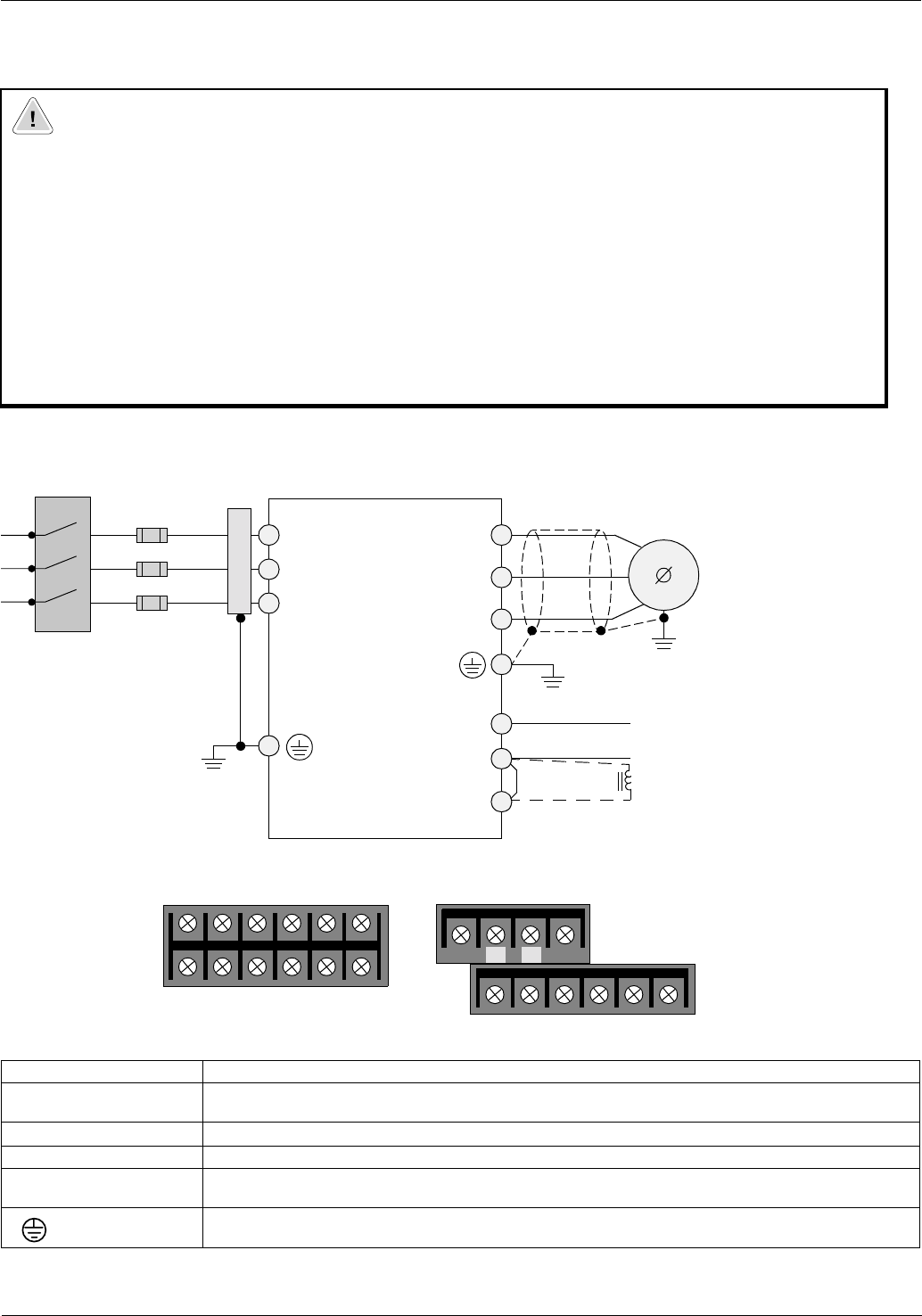
Figure 2.3 Power wiring block diagram
Input power supply
Figure 2.4 Power terminal block descriptions
1 DC Bus Reactor would be used to assist in limiting harmonic distortion from the 161 to the line and reducing capacitive heating due to low impedance lines.
ATTENTION
• Ensure that the input voltage corresponds to the voltage indicated on the product nameplate.
• In normal operation apply the START/STOP commands via the control terminals or the control
panel and not by disconnecting and reapplying input power to the drive or motor contactor. If it
is necessary to use this method for starting and stopping, or if frequent cycling of power is
unavoidable, make certain it does not occur more than once every 5 minutes. Do not install any
capacitors or suppressors to the drive output terminals.
• Exercise particular caution if automatic restart is activated. To prevent injuries caused by
automatic restarting of the drive following a power failure, install a switching component at the input
that is deactivated in the event of a power failure and that may only be manually switched
on again on return of the power supply (e.g. contactor etc.).
• Suitable for use on a circuit capable of delivering not more than 5,000 rms symmetrical amperes,
240V maximum.
Terminal Description
L1, L2, N/L3 Connection to incoming power. For single phase input applications, connect the AC input power to
input terminals L1 and N/L3
U/T1, V/T2, W/T3 Motor connections
-/+ DC Bus connection
+1
+
These terminals are connected by a jumper. For applications requiring a DC bus reactor, remove
the jumper prior to installing the third party device.
Protective earth ground connection
Disconnect
Device
Fuses
Optional
Filter
L1
Bulletin 161
L2
N/L3
U/T1
V/T2
W/T3
DC
Bus
–
+
+1
3
Motor
Optional
DC Bus Reactor
1
L1
AA01 - AA03 Power terminal block
L2 N/L3 U/T1 V/T2 W/T3
L1
All ratings except AA01 - AA03 Power terminal block
L2 N/L3 U/T1 V/T2 W/T3
***
+1 –+
+1(/) –+
*
Not Used