
Manual
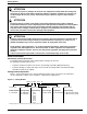
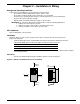
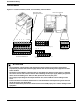
Table Of Contents
- 161 Appx_a.pdf
- New 161_bkcvr.pdf
- 161 Chptr_3.pdf
- Programming Keypad
- Programming Examples
- Initial Power Up
- Scrolling through parameter groups
- Operation of the Drive via the Fixed Keypad
- Note: The factory default settings for the “U” version drive is three wire control (PC03 is set t...
- Note: The direction of rotation is controlled by PF04 - [Start Key Direction]. Refer to page 22 o...
- Activating the Speed Pot on the Keypad
- Parameter A01-[Frequency Command Select] is used to select the source of the frequency command.
- Note: The output frequency of the Bulletin 161 can also be controlled digitally from the keypad b...
- Note: If a digital input is set as 27 (UP) or 28 (DWN), when activated these inputs will also cha...
- Restoring Factory Defaults
- Parameter Descriptions
- 161 Chptr_2.pdf
- 161 Chptr_4.pdf
Installation & Wiring
6
Terminal Blocks
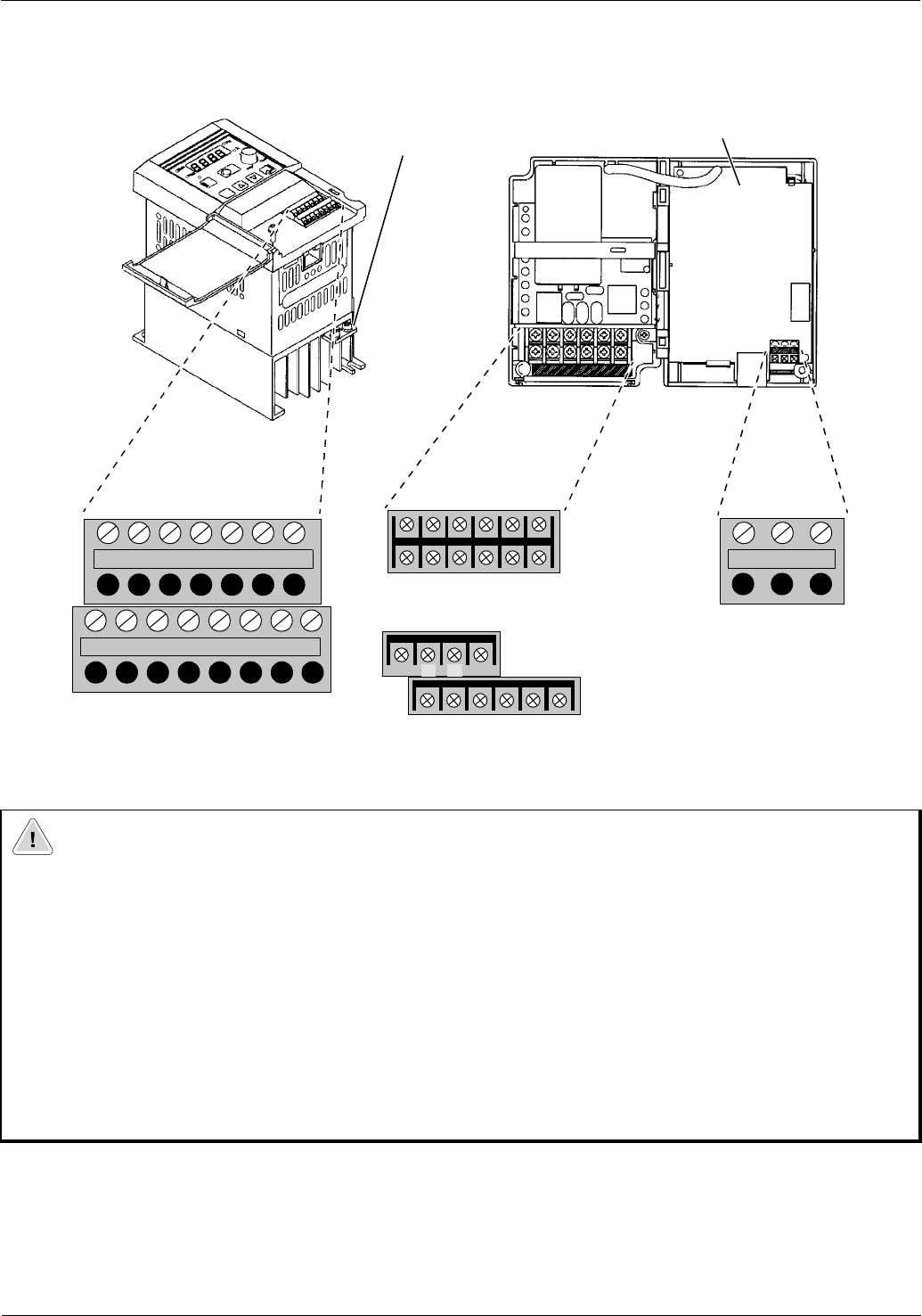
Figure 2.2 Location of Power, Control, and Fault Relay Terminal Blocks
ATTENTION
• The installation, commissioning and maintenance of these drives may only be carried out by
experienced personnel who are thoroughly familiar with the functioning of the equipment and the
entire machine.
• The devices feature DC-bus capacitors that are energized even when the input supply is switched
off. For this reason wait at least 5 minutes after switching off the input supply before you open the
device and start working on it. Take care that you do not touch any live parts.
• Do not apply input voltage to the output terminals U/T1, V/T2 and W/T3 as drive damage could
occur.
• Contact the motor or machine manufacturers if standard motors with frequencies greater than 60
Hz will be used in your application.
• Failure to follow these precautions could result in severe bodily injury, loss of life or damage to the
equipment.
L
HO0I LFM
Control terminal block
CM2 12 11
54321
L1
Power terminal block, AA01 - AA03 ratings only
L2 N/L3 U/T1 V/T2 W/T3
L1
Power terminal block, all ratings except AA01 - AA03
L2 N/L3 U/T1 V/T2 W/T3
***
+1 –+
+1(/) –+
P24 AL0
Fault relay
AL1 AL2
*
Not Used
Protective earth
ground connection
Front cover opened
terminal block