Allen-Bradley Bulletin 161 AC Drive (Series B) 0.2-3.7kW (0.3 to 5 hp) FRN 2.
Important User Information Solid State equipment has operational characteristics differing from those of electromechanical equipment. ªSafety Guidelines for the Application, Installation and Maintenance of Solid-State Controlsº (Publication SGI-1.1) describes some important differences between solid-state equipment and hardwired electromechanical devices.
Table of Contents 1. Getting Started ........................................................................................ Important Precautions Conventions used in this manual Catalog Number Explanation Receiving Your New Drive Nameplate Label Drive Features p.1 p.2 p.2 p.3 p.3 p.4 2. Installation & Wiring ...............................................................................
5. Specifications & Dimensions ................................................................ Technical Data Dimensions Accessories p.39 p.40 p.42 A. CE Conformity ........................................................................................ CE Compliance General Notes and Instructions Essential Requirements for a Conforming EMC Installation Motor Cable Control Cable ii p.43 p.43 p.43 p.43 p.
Chapter 1 – Getting Started Important Precautions In addition to the precautions listed throughout this manual, you must read and understand the following statements which identify hazards associated with AC drives. ATTENTION The Bulletin 161 drive contains high voltage DC bus capacitors which take time to discharge after removal of input power. Before working on the drive, wait five minutes for capacitors to discharge to safe voltage levels.
Getting Started ATTENTION • To prevent any injuries or damage, do not touch any components located within the housing with your hands or with any other objects while input voltage is applied or if the DC-bus capacitors are not discharged. Do not carry out any work on the wiring or check any signals if input voltage is applied. ATTENTION • Ensure that the input voltage corresponds to the voltage indicated on the product nameplate.
Getting Started Receiving Your New Drive It is your responsibility to thoroughly inspect the equipment before accepting shipment from the freight company. Check the item(s) received against your purchase order. If any items are obviously damaged, do not accept delivery until the freight agent notes the damage on the freight bill. Unpacking Remove all packing material, wedges, or braces from within and around the drive. Remove all packing material from the heat sink.
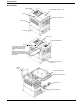
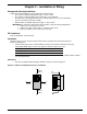
Getting Started Drive Features Fixed keypad Control terminal block cover Screw RS422 serial interface Enclosure Heat sink Front case Control terminal block Screw To wire the power terminals and fault relay, loosen the screw and open the front case. Note that for ratings AA01AA03 the screw is located under the control terminal block cover.
Chapter 2 – Installation & Wiring Storage and Operating Conditions Follow these recommendations to prolong drive life and performance: • Store within an ambient temperature range of –25oC to 70oC. • Store within a relative humidity range of 20 to 90%, non-condensing. • Avoid storing or operating the drive where it could be exposed to a corrosive atmosphere. • Protect from moisture and direct sunlight. • Operate within an ambient temperature range of –10oC to 40oC.
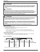
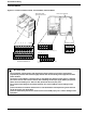
Installation & Wiring Terminal Blocks Figure 2.
Installation & Wiring Power Wiring Precautions: ATTENTION • Ensure that the input voltage corresponds to the voltage indicated on the product nameplate. • In normal operation apply the START/STOP commands via the control terminals or the control panel and not by disconnecting and reapplying input power to the drive or motor contactor.
Installation & Wiring Power Terminal Block Wiring Specifications Model AA01-AA02 AA03 AA04, DA01 AA05-AA10, DA02-DA03 AA15 Screw Size M3.5 M3.5 M4 M4 M4 Max/Min Wire Size mm2(AWG) 2.1 – .75 (14-18) 2.1 – 1.3 (14-16) 5.3 – 1.3 (10-16) 5.3 – 2.1 (10-14) 5.3 – 3.3 (10-12) Max/Min Torque Nm (lbin) 0.9-0.8 (8.0-7.0) 0.9-0.8 (8.0-7.0) 1.3-1.2 (11.5-10.6) 1.3-1.2 (11.5-10.6) 1.3-1.2 (11.5-10.
Installation & Wiring Control Wiring Requirements • • • • Run all signal wiring in either a shielded cable or separate metal conduit. Do not exceed control wiring length of 20 meters (65.6 feet). Use Belden 8760 (or equivalent) –18 AWG (0.750mm2), twisted pair, shielded or 3 conductor. Avoid crossing the power lines or motor lines with the control wires. If they must cross, ensure that they cross at right (90o) angles.
Installation & Wiring Control Terminal Descriptions ATTENTION • DO NOT jumper or short circuit terminals H and L or P24 and L or drive damage could occur. The following table gives a description of each of the terminals on the control terminal block as well as the fault relay: Control Terminal P24 1 2 Function 24 V DC Programmable Digital Inputs. 26V max, 5KΩ input impedance.
Installation & Wiring Control Terminal CM2 Function Reference potential for outputs 11 and 12 Description Transistor output, max. 27 Vdc, 50 mA 11,12 CM2 12 Programmable Digital Output 11 Programmable Digital Output AL0 Fault Relay – 24V + The outputs can be programmed as either NO (active high) or NC (active open) contacts using PC31-[Digital Output 11Logic] and PC32-[Digital Output 12 Logic].
Installation & Wiring Programmable Digital Input (Control terminal block inputs 1 through 5) Functions The function of the digital inputs 1 through 5 are programmed via the corresponding PC01 [Digital Input 1] through PC05 - [Digital Input 5]. The following programming guidelines must be followed: • No two inputs can be programmed for the same function. • The PTC input (setting 19) is only programmable on input terminal 5.
Installation & Wiring C01 - C05 Setting 11 Alpha Setting {FRS} Function Description Coast to Stop The motor voltage will be switched off immediately and the motor will coast. This function can be programmed to operate in two different modes via Pb88-[FRS Select]. synchronization of motor speed 0Hz start Run (NO) Input 11 {FRS} (NO) Motor speed Waiting time Note: The drive will start when 11 {FRS} input is removed without reissuing a start command even if in 3 wire (momentary) control.
Installation & Wiring C01 - C05 Setting 18 Alpha Setting {RS} Function Description Reset Used to clear a fault condition. If a 18 {RS} command is given during operation, the output IGBT’s are switched off and the motor will coast. min 12 ms 18 {RS} (NO) Fault indication 19 {PTC} PTC Input ca. 30 ms This input can only be programmed to digital input terminal 5 and the PTC should be referenced to terminal L.
Chapter 3 – Parameters & Programming ATTENTION Wait at least 6 seconds after programming the Bulletin 161 before issuing a start, reset command, or switching off the power supply. Failure to wait 6 seconds, could result in failure to recognize programming changes, which could lead to bodily injury or damage to the equipment. Programming Keypad The keypad is located on the front panel of the drive.
Parameters & Programming Figure 3.2 Programming Guide d01 A01 d09 A98 F01 b01 F04 b89 C01 A .. B .. C91 C .. Scroll Thru Parameter Groups Press SEL to enter parameter group. View Save Parameter Change Entered Value Parameter Parameter Value Value Scroll Thru Parameter Numbers Programming Examples In this section you will find four different programming examples to help you program the 161 drive.
Parameters & Programming Action Description 6. Press the SELect Key to view the parameter value stored in PC21 - [Digital Output 11]. Display 01 7. Press the SELect Key again to exit from the parameter value back to the parameter number without changing the stored value. C 21 8. Press the SELect Key again to exit from the parameter number to the parameter group display.
Parameters & Programming Restoring Factory Defaults This example will show you how to reset the factory defaults of the drive. Action Description 20. Press the Down Key to advance to the b parameter group. Display b-- 21. Press the SELect key to enter into the b parameter group. b 01 22. Press the Up Key to scroll through the parameters until parameter b84 [Reset Functions] is displayed. b 84 23.
Parameters & Programming Figure 3.
Parameters & Programming Parameter Tree cont.
Parameters & Programming Parameter Descriptions D Group - Display and Diagnostic Parameters (Read Only) This group of parameters consists of commonly viewed drive operation conditions such as output frequency. All parameters in this group are Read Only. Parameter Parameter Name / Description Number Display and Diagnostic Functions d01 [Output Frequency] Displays the output frequency to the motor. d02 [Output Current] Displays the output current to the motor.
Parameters & Programming F Group – Basic Function Parameters Parameter Number Parameter Name / Description Basic Functions F01 [Frequency Command] When parameter A01- [Frequency Command Select] is set to 00 or 01, this parameter will display the commanded frequency. When PA01 - [Frequency Command Select] is set to 02, this parameter can be used to change the commanded frequency on the fly and write the value into parameter A20 [Internal Frequency].
Parameters & Programming Parameter Number Parameter Name / Description Min./Max Range Basic Functions A03 [Base Frequency] Set value to rated nameplate frequency of motor Command Frequency Voltage 100% 0 Start Frequency b82 A04 Base Frequency A03 Frequency Maximum Frequency A04 Minimum Frequency A62 Units Factory Defaults 50/360 1 Hz U1 60 K1 50 50/360 1Hz 60 50 0.0/360.0 0.1 Hz U1 0.0 K1 0.0 0.0/360.0 0.1 Hz 0.0 0.
Parameters & Programming 1 U = 50Hz default settings, K = 50 Hz default settings. Settable using Pb85 – [Factory Default Select] Parameter Number Min./Max Range Units Factory Defaults 0.0/360.0 0.1 Hz U1 60.0 0.0/360.0 0.1 Hz 0.0 0.0 0.0/360.0 0.1 Hz 3.0 0.0 0.0/360.0 0.1 Hz 5.0 0.0 0.0/360.0 0.1 Hz 10.0 0.0 0.0/360.0 0.1 Hz 15.0 0.0 0.0/360.0 0.1 Hz 20.0 0.0 0.0/360.0 0.1 Hz 25.0 0.0 0.0/360.0 0.1 Hz 30.0 0.0 0.0/360.0 0.1 Hz 35.0 0.0 0.0/360.0 0.1 Hz 40.0 0.
Parameters & Programming Parameter Number Parameter Name / Description Min./Max Range V/F Characteristics / Boost A41 [Boost Select] Used to select auto or manual boost Settings: 00=Manual Boost 01=Auto Boost A42 [Manual Boost Voltage] Sets the boost level as a percent of PA82 - [Base Voltage]. This Parameter can be changed while motor is running. Voltage 100% Units Factory Defaults U1 00 K1 00 00/01 Numeric Value 0/99 Numeric Value 25 11 0.0/50.0% 0.1% 2.0 10.
Parameters & Programming Parameter Number DC Brake A51 A52 A53 A54 A55 Parameter Name / Description [DC Brake Enable] Used to enable/disable DC injection braking Settings: 00=Disabled 01=Enabled [DC Brake Start Frequency] Sets the frequency at which the DC brake will become active. [DC Brake Wait Time] Sets the time the drive will wait after PA52 [DC Brake Start Frequency] before applying PA54 - [DC Hold Voltage].
Parameters & Programming Parameter Number Parameter Name / Description Operating Frequency Range cont. A67 [Skip Frequency 3] Sets a frequency at which the drive will not output continuously. A68 [Skip Frequency Band 3] Sets the bandwidth around PA67 - [Skip Frequency 3]. The bandwidth is 2x PA68 [Skip Frequency Band 3] with ½ the band below and ½ the band above PA67 - [Skip Frequency 3]. PID Controller A71 [PID Enable] Used to disable / enable the use of PID control.
Parameters & Programming Parameter Number Parameter Name / Description Min./Max Range Operating Frequency Range cont. A94 [Accel / Decel 2 Select] Used to determine when the PA92 – [Accel Time 2] and PA93 - [Decel Time 2] are used. Settings: 00=Digital inputs (C01-C05) set to 09{2CH} 01=Automatic if frequency programmed in PA95 - [Accel 2 Start Frequency]/ PA96 - [Decel 2 Start Frequency] is reached.
Parameters & Programming b Group – Advanced Control and Protection Parameters Parameter Number Parameter Name / Description Min./Max Range Automatic Start After a Fault b01 [Restart Mode Select] Selects the restart mode for the drive Settings: 00=Fault indication 01=0 Hz start 02=Synchronize. 03=Synchr.
Parameters & Programming Parameter Number Parameter Name / Description Current Limit b21 [Current Limit Select] Selects the mode for current limit. Settings: 00=Inactive 01=Active 02=Inactive in acceleration b22 b23 [Current Limit] Sets the maximum output current allowed before current limiting occurs. Value set in percent of drive rated output current. [Current Limit Decel Time] Sets the deceleration time when the current limiting occurs.
Parameters & Programming Parameter Number Parameter Name / Description Initialization / Adjustment Function b81 [Output FM Adjustment] Sets the multiplier applied to output duty cycle for the FM analog signal. This Parameter can be changed while motor is running. Min./Max Range Units Factory Defaults 0/255 N/A U1 80 K1 80 b82 [Start Frequency] Sets the frequency at which the drive will start. Refer to diagram in PA03 – [Base Frequency] 0.5/9.9 0.1 Hz 0.5 0.
Parameters & Programming Parameter Number Parameter Name / Description Initialization / Adjustment Function b88 [FRS Select] Selects operation of the drive after a digital input (C01 – C05) setting 11{FRS} input is removed. Settings: 00=0 Hz start 01=Synchronization of motor speed after waiting period programmed via Pb03 – [Restart Time]. b89 [Reserved] Reserved for Future Use, DO NOT CHANGE b92 [Reserved] Reserved for Future Use, DO NOT CHANGE 1 Min.
Parameters & Programming C Group – Intelligent I/O and Communication Parameters This parameter group is used to program the functions of the digital and analog I/O. ATTENTION • • • All digital inputs respond to level sensitive commands. Inputs do not require a voltage transition (cycle) after a fault condition is cleared, after input power cycling or after programming the logic of the digital input. All digital inputs can be programmed as NO or NC.
Parameters & Programming Parameter Parameter Name / Description Number Outputs 11, 12, FM, AL0-AI1 C23 [Output FM Select] Sets the operation of the output FM. Settings: 00={A-F} (Analog Output Frequency) 01={A} (Motor Current) 02={D-F} (Digital Output Frequency) Refer to control inputs table in Chapter 2 for setting descriptions. C31 [Digital Output 11-12 Logic] Sets the digital outputs to be NO or NC contacts.
Chapter 4 – Faults & Troubleshooting Fault Information This chapter provides information to guide you in troubleshooting the drive. Included is a list and description of drive faults and problems that may occur. How to Clear a Fault When a fault occurs, the cause must be corrected before the fault can be cleared. After corrective action has been taken, any of the following actions will clear the fault. • Press the stop button on the Keypad.
Faults & Troubleshooting Fault Number Fault Name E 14 Ground Fault Fault Description Corrective Action E 21 There was a ground fault at the motor output terminals. Excess Input The input voltage is higher than Voltage permitted. Overtemperature Excessive heat has been detected fault inside the drive. E 35 PTC circuit triggered. E 60 Communication Error E 15 The resistance from the external thermistor was too large. (Greater than 3 kΩ) A loss of communication has occurred.
Faults & Troubleshooting Problem The motor does not accelerate properly. The speed of the motor does not match the frequency. 1. 2. 3. 4. 5. 1. 2. The motor runs unstable. 3. 4. 1. 2. 3. The parameters stored do not match the values 1. entered. No entries can be made. 1. The electronic motor protection (fault E05) is triggered. 1. 2. Corrective Action Check to see that a frequency has been commanded. Check to see if a preset frequency has been selected. Check to see if the motor load is too high.
Faults & Troubleshooting This Page Intentionally Blank 38
Chapter 5 – Specifications & Dimensions Technical Data Series Type Drive rating kW (HP) 115V Input rated current (A) 230V 1F Input rated current (A) 230V 3F Input rated current (A) Output rated current (A) Power Dissipation (W) Mass (kg) Input voltage (V) Output voltage Type of protection PWM carrier frequency V/Hz characteristics Type of control Output frequency Accuracy of frequency command Frequency resolution Overload capacity Starting torque DC brake Analog inputs Digital inputs Analog outputs Digital
Specifications & Dimensions Figure 5.1 Bulletin 161 Dimensions (All dimensions are in millimeters and (inches). AA01 / AA02 / AA03 AA04 / AA05 Mass Kg (lb) AA04/AA05 1.3 (2.87) Mass Kg (lb) AA01 0.7 (1.54) AA02/AA03 0.85 (1.87) AA07 AA10/AA15 Mass Kg (lb) AA07 2.2 (4.85) 40 Mass Kg (lb) AA10/AA15 2.8 (6.
Specifications & Dimensions DA04 DA01 / DA02 Mass Kg (lb) DA01 1.1 (2.42) DA02 1.2 (2.64) Mass Kg (lb) DA04 1.5 (3.
Specifications & Dimensions Accessories Line Filter Module Specifications Nominal Voltage [V] 120 +5% 120 +5% 240 +5% 240 +5% 240 +5% 240 +5% 240 +5% 240 +5% Line Filter Module 161S-RFD-10-B 161S-RFD-16-C 161S-RFA-7-A 161S-RFA-12-B 161S-RFA-22-C 161-RFA-4-A 161-RFA-7-B 161-RFA-20-C Nominal Current at 40°C [A] 10 A 16 A 7A 12A 22A 4A 7A 20A Leakage Current at 50 Hz (mA) < 3.5 < 3.5 < 3.5 < 3.5 < 15 < 3.5 < 3.5 < 3.
Appendix A – CE Conformity CE Compliance This drive is a component intended for implementation in machines or systems for the industrial environment. It is CE marked for conformity to the Low Voltage (LV) directive 73/23/EEC when installed as described. It also has been tested to meet the Council Directive 89/336 Electromagnetic Compatibility (EMC). The standards used for this testing are, LV: EN50178, EN60204-1, EN60950, EMC: EN61800-3 (EN55011, Group 1, Class B (Industrial Environment)).
CE Conformity This Page Intentionally Blank 44
CE Conformity 45
Publication 0161-5.0MU – March, 2001 Supersedes 161-5.0MU dated September, 2000 NB591XA Copyright 2001 Rockwell International Corporation. All rights reserved.