Bulletin 161 Single Phase AC Drive 1~ / 200-240V 0.2 – 2.
Bulletin 161 Table of contents 1. Checking the scope of supply..................................................................................................... 1 2. Structure of the device................................................................................................................. 2 3. Installation .................................................................................................................................... 4 4. Wiring...........................................
Bulletin 161 ii
Bulletin 161 Attentions and safety guidelines Before installing the Bulletin 161 drive and putting it into operation, please read this user manual carefully and take note of all the Attentions and safety guidelines. Always keep this product manual near the Bulletin 161 drive so that it is easily accessible. Definition of the guidelines ATTENTION Failure to comply with these precautions may result in death, serious personal injury or substantial damage to equipment.
Bulletin 161 ATTENTION • To prevent any injuries or damage, do not touch any components located within the housing – either with your hands or with any other objects – if mains voltage is applied or if the DC-bus capacitors are not discharged. Do not carry out any work on the wiring or check any signals if mains voltage is applied. • Exercise particular caution if automatic restart is activated.
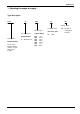
Bulletin 161 1. Checking the scope of supply Type description 161S - A A04 N PK Fifth Position Fourth Position Third Position Second Position Voltage Rating First Position Bulletin Number An “S” in the bulletin Number denotes a single phase input voltage A 200-240V 1∅ Current Rating A01 A02 A03 A04 A05 A07 A10 Enclosure Type N PK Integrated Programmer Keypad IP20 1.4 A 2.6 A 3.0 A 4.0 A 5.0 A 7.1 A 10.
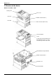
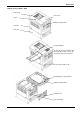
Bulletin 161 2. Structure of the device Bulletin 161S-AA01 / AA02 control panel front cover enclosure RS422 serial interface ( heat sink PE connection (M4 screw) control terminals screw To wire the power terminals and fault indication relay, loosen the screw and open the control unit.
Bulletin 161 Bulletin 161S-161-AA03 / AA04 control unit front cover screw RS422 serial interface enclosure heat sink control terminals To wire the power terminals and fault indication relay, loosen the screw and open the control unit.
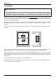
Bulletin 161 3. Installation ATTENTION • Environmental influences such as high temperatures and high relative humidity are to be avoided as well as dust, dirt and corrosive gases. The mounting location should be well ventilated and not exposed to direct sunlight. Install the device on a non-flammable, vertical wall that does not transmit any vibrations. Attention! Do not apply mains voltage to the output terminals U/T1, V/T2 and W/T3.
Bulletin 161 4. Wiring ATTENTION • The installation, commissioning and maintenance of these drives may only be carried out by experienced personnel who are thoroughly familiar with the functioning of the equipment and the entire machine. • The devices feature DC-bus capacitors that are energized even when the mains supply is switched off. For this reason wait at least 5 minutes after switching off the mains supply before you open the device and start working on it.
Bulletin 161 4.1 Connection and description of the power terminals The control unit must be open in order to be able to wire the power terminals. Do not apply mains voltage to the drive connection terminals U/T1, V/T2, and W/T3 as this will result in damage to equipment. The Bulletin 161 drives feature an electronic overload protection to monitor the drive current. In the case of multi-motor operation, thermal contacts or PTC resistors must be used for each motor.
Bulletin 161 Terminal L1, N U/T1 V/T2 W/T3 + _ Function Mains connection Motor connection Description 1 ~ 200 - 240 V +/- 10%, 50/60 Hz +/- 5% Star or delta connection of the motor in accordance with the rated voltage DC-bus connection Connection for brake chopper + +1 Connection for DC-bus reactor If an DC-bus reactor is connected, remove the copper bridge. Ensure that the bridge between the terminals + and +1 is installed if there is no DC-bus reactor installed.
Bulletin 161 4.2 Connection and description of the control terminals When using the transistor outputs 11, 12 - CM2 install a recovery diode parallel to the relay used. Otherwise the switching relay could damage the output. Do not short-circuit the terminals H and L or P24 and L. The control wires must be installed separately from the power lines and motor lines. They may not exceed 20 m in length. To improve noise immunity, the control wires should be screened (refer to Appendix A).
Bulletin 161 ATTENTION • If an input is used as [FW] or [RV] and programmed as a Normally Closed (NC) contact, the drive will start as soon as the power supply is switched on – without the input being triggered. • Please note that a start command should not be issued if an input is used as [FW] or [RV] when the power is switched on otherwise the motor will start immediately; wait at least 2s after switching on the power before issuing a start command.
Bulletin 161 Terminal Function H 10 V reference voltage for frequency command default O Analog input Frequency command 0-10 V Description 3RWHQWLRPHWHU 9 P$ WR N2KP QRPLQDO 9 QRPLQDO P$ + 2 2, / 3( OI L CM2 + 2 2, / 3( ,QSXW LPSHGDQFH N2KP + 2 ,QSXW LPSHGDQFH 2, 2KP / 3( For analog input reference adjustment see parameters A11...A16. Input OI for 4-20 mA is activated when the digital input is set to [AT] (see parameter C01...C05).
Bulletin 161 Overview of the functions of the programmable digital inputs 1 - 5 The digital inputs 1 to 5 can be programmed for 15 different functions. With exception of the PTC input (programmable on input 5 only), every input can be programmed for any function. Parameters cannot be programmed for two different inputs at the same time. The various functions are listed and described in the table below. Programming is done via parameters C01...C15 (parameters C01...
Bulletin 161 Input / Function [USP] 13 Function Restart lock Description The restart lock prevents a uncontrolled restart of the Bulletin 161 drive when – after power off – the power supply returns and a start command is issued immediately or straight afterwards.
Bulletin 161 PLC control Control with internal control voltage L100-...NFE/HFE Bulletin 161 PLC 24 V P24 1 2 3 4 5 L 0V Control with external control voltage L100-...
Bulletin 161 5. Programming ATTENTION Wait at least 6s after programming the Bulletin 161 before issuing a start or rest command, switching off the power supply or pressing any other key on the control panel. 5.1 Description of the control panel The Start-key will start operation in the direction of rotation defined under parameter F04; not active when control is via the terminal block. 4-position LED display to display parameters and operating data. Stop/Reset-key.
Bulletin 161 ATTENTION Before switching on the power supply the following points must be observed: • Check that the mains lines and motor lines are connected properly. • The control wires must be connected at the correct terminals. • The drive must be earthed correctly and must be installed vertically on a wall made from nonflammable material. • All screws and terminals must be tightened.
Bulletin 161 5.5 Overview of the parameters Parameter Display function number Remarks Display and diagnostic functions d01 Output frequency [Hz] d02 Motor current [A] d03 Direction of rotation F : Forward r: : Reverse 0 : Stop d04 Actual value x actual value factor [%] (only available if the PID controller is active) The actual value factor is set in param. A75 in the range from 0.01 ... 99.99 The default setting is 1.0. d05 Status of digital inputs 1 ...
Bulletin 161 Parameter Function number Basic parameters Basic value Setting range A01 Frequency command select 01 A02 Start command select 01 A03 Base frequency 50 00: Frequency Pot 01: Input O/OI 02: Param.
Bulletin 161 Parameter Function number V/F characteristics / boost Basic value Setting range A41 Boost select 00 00: Man. boost 01: Auto boost A42 Manual boost 11 0 – 99 A43 Max. boost at % of base frequency 10 0 - 50% A44 V/F select 00 00: Constant 01: Variable A45 Maximum output voltage 100 50 - 100% A51 DC Brake active / inactive 00 00: inactive 01: active A52 DC Brake Starting frequency 0.5 0.5 – 10 Hz A53 DC Brake Waiting time 0.
Bulletin 161 Parameter Function number PID controller Basic value Setting range A71 PID controller active / inactive 00 00: inactive 01: active A72 PID Proportional Gain 1.0 0.2 – 5.0 A73 PID Integral Gain 1.0 0.0 - 150 s A74 PID Differential Gain 0.0 0.0 - 100 A75 Process reference scale factor 1.0 0.01 – 99.
Bulletin 161 Parameter Function number Automatic start after a fault Basic value Settings range b01 Restart mode select 00 00: Fault indication 01: 0 Hz start 02: Synchr. 03: Synchr. + stop b02 Permissible power failure time 1.0 0.3 - 25 s b03 Waiting time before restart 1.0 0.
Bulletin 161 Parameter Function number Digital inputs 1 – 5 Basic value Setting range C01 Digital input 1 00 C02 Digital input2 01 C03 Digital input 3 02 C04 Digital input 4 03 C05 Digital input 5 18 00: [FW] Forward 01: [RV] Reverse 02: [CF1] Preset. freq. 03: [CF2] Preset freq. 04: [CF3] Preset freq. 05: [CF4] Preset freq. 06: [JG] Jog nd 09: [2CH] 2 ramp 11: [FRS] Coast stop 12: [EXT] Ext. trip 13: [USP] unintention. start protection 15: [SFT] Softw. lock 16: [AT] 4-20 mA sel.
Bulletin 161 6. Fault indications The Bulletin 161 drives are provided with protective devices such as protection against excessive current, excessive voltage and under-voltage. When one of the many protection functions is triggered the output voltage will be switched off – the motor will freewheel and the device will remain in the fault indication mode until the fault indication has been cleared.
Bulletin 161 Fault indication E 09 E 11 Description E 13 E 14 E 15 E 21 Corrective action DC-bus undervoltage Check the input voltage. Brief voltage dips occur or the mains voltage is reduced to 150160V Processor error Possible influence of electromagnetic fields on the drive? Examine the environment of the drive and external wiring for causes of the fault (e.g. terminal bar). Is the drive defective? Have the device serviced by customer support.
Bulletin 161 Other displays Display Description A reset signal has been issued. The Bulletin 161 drive is in standby mode. - - - The mains voltage has been switched off. The waiting time before automatic restart has expired (see parameter b01 - b03). 24 EU The factory setting has been selected and the drive is in the initialisation phase (see parameters b84, b85). The parameters for the European market are loaded ___ No data present (e.g.
Bulletin 161 7. Faults and troubleshooting Fault The motor does not start. There is no voltage at terminals U/T1, V/T2, W/T3. Voltage is applied to terminals U/T1, V/T2, W/T3 The direction of rotation of the motor is incorrect. The motor does not accelerate. Possible cause Corrective action Is there mains voltage at the input terminals L1, N? If so, is the LED display lit? Check connections L1, N and U/T1, V/T2, W/T3. Switch on the mains voltage.
Bulletin 161 Fault The motor runs unstable. The speed of the motor does not match the frequency. Possible cause Corrective action Do sudden high load changes occur? Choose a drive and motor with a higher rating. Reduce sudden load changes. Resonant frequencies occur in the motor. Blank out the frequencies in question with frequency jumps or change the reference frequency. The mains voltage is not constant.
Bulletin 161 8. Technical Data Series Type Bulletin 161SAA01 AA02 AA03 AA04 AA05 AA07 AA10 Drive rating (kW) 0.2 0.4 0.55 0.75 1.1 1.5 2.2 Input rated current (A) 3.1 5.8 6.7 9.0 11.2 16.0 22.5 Output rated current (A) 1.4 2.6 3.0 4.0 5.0 7.1 10.0 Mass (kg) 0.85 0.85 1.3 1.3 2.2 2.2 2.8 Mains voltage (V) 1 ~ 200 V -10% to 240 V + 5%, 50/60 Hz +/- 5% Output voltage 3 ~ 0 - 200 ...
Bulletin 161 9. Dimensions Bulletin 161S-AA01 / AA02 Bulletin 161S-AA03 / AA04 98 67 Hz PRG A Hz RUN MAX SEL 118 MIN 120 110 PRG A MIN 130 RUN MAX SEL 10 5 10 5 5 Ground Terminal Ground Terminal 4 7 80 110 7 4 Main Circuit Terminal Main Circuit Terminal Alarm Terminal 129 Control Circuit Terminal Bulletin 161S-AA05 / AA07 Bulletin 161S-AA10 140 128 MIN MAX RUN Air Hz 180 A 168 Hz PRG 180 168 140 128 RUN Control Circuit Terminal 2.5 2.
Bulletin 161 10. Accessories Line Filter Module Specifications Nominal Voltage Line Filter Module [V] 161S-RFA-6-A 161S-RFA-9-B 161S-RFA-22-C 240 +5% 240 +5% 240 +5% Current: Nominal Current at 40°C [A] Leakage Current at 50 Hz (mA) Test voltage [VDC for 2s] ph. / ph; ph. / ground 2x 6A 2 x 10 A 2 x 23 A < 3,5 < 3,5 < 10 1400 / 2800 1400 / 2800 1400 / 1400 at 40°C ambient temperature Input wire Output cable max. cross cross section section [mm2] [mm2] (L) 4/4 (N) 4/4 4/4 3x1.5 3x1.5 3x2.
Bulletin 161 Appendix A: CE Conformity The Bulletin 161 is CE marked for conformity to the Low Voltage (LV) Directive 73/23/EEC when installed as described. It also has been tested to meet the Council Directive 89/336/EEC Electromagnetic Compatibility (EMC). The standards used are: LV EMC Important: EN50178, EN60204-1, EN60950 Emissions: Immunity: EN61800-3 (EN55011, Group 1, Class B) EN61800-3 (Industrial Environment).
Bulletin 161 Compliance of the Bulletin 161 drive to the conducted emissions levels with appropriate line filter module is as follows: PWM Carrier Frequency <16 kHz <5 kHz <16 kHz Motor cable length 10 m 20 m 50 m Limit Class B Class B Class A 2. All motor cables must be shielded cable, or be in grounded metal conduit. 3. All control and signal wiring must use shielded cable or be in grounded metal conduit. 4. Grounding of equipment and cable shields must be solid, with low impedance connections. 5.
Bulletin 161 General instructions for an EMC compliance installation Enclosure • Typical IEC metal enclosures are adequate. • The ground connection of the enclosure must be solidly connected to the PE terminal of the drive. Good conductivity must be assured – grounding must provide a low impedance path for high frequency signals. • All wiring, except input power leads, must be shielded cable. • Input power, output power and control wiring inside the enclosure must be physically separated.
Publication 161-5.0EN – May 1999 Copyright 1998 Rockwell International Corporation.