
Manual

InterBus Parameter Descriptions and Data Protocol 5–3
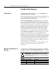
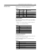
Data from IB1 Slave to InterBus
Master
Speed Feedback, displayed by Register 1, is scaled in RPM according
to P66 - [RPM Scaling].
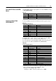
Table 5.B
Control and Status Word
DRIVECOM 20/21
Control and Status word bits are defined as follows (speed control):
Table 5.C
Control Word (Bit definition)
To start the drive, set the control word (Low Byte) from 6 to Fh.
To stop the drive, set the control word (Low Byte) to 6.
To control the drive via Terminal Block (TB3), the Control Word Low
Byte must be set to 06h (state READY TO SWITCH ON).
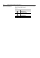
Table 5.D
Status Word (Bit definition)
* Internal speed reference/feedback is computed in 0.1Hz increments.
Due to rounding issues speeds in RPM may differ.
Resolution error in RPM = P66 * 0.05.
Example: for P66 = 16.6 the possible error is 1 RPM.
Register No. Register (Words) Description
0 Status Word According to DRIVECOM 20
1 Speed Feedback 160 Drive Output Frequency (motor RPM)
2 Diagnostics reserved
Bit No. DRIVECOM 20 Control SSC160
0 Switch-on 1 = Switch-on
1 Disable voltage 0 = Disable
2 Fast Stop 0 = Stop
3 Enable Operation 1 = Enabled
4 reserved
5 reserved
6 reserved
7 Reset Fault 0 to 1 Transition = Reset
8 to 15 reserved
Bit No. DRIVECOM 20 Status SSC160
0 Ready to switch-on 1 = Ready
1 Switched-on 1 = Switched-on
2 Operation enabled 1 = Enabled
3 Fault 1 = Fault
4 Voltage-disabled 0 = Disabled
5 Fast stop 0 = Stop
6 Switch-on-disabled 1 = Disabled
7 reserved
8 reserved
9 Remote 0 = Local
10 Speed Ref. Reached 1 = Speed Ref. Reached *
11 Speed limited 1 = Speed limited *
12 reserved
13 reserved
14 Reverse Disabled 1 = Reverse Disabled
15 Direction 1 = Reverse (running)