
Manual


Installation and Wiring 3–7
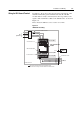
Connecting the Communication
Cable to the Module
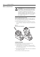
Follow these steps to connect your module.
1. Verify that the cable/connector is correctly wired
(See Figure 3.6).
2. Locate the D-shell (IN) connector at the base of the IB1 Module.
3. Plug cable/connector into the IB1 D-shell connector and secure.
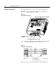
4. Extend the network via the D-shell
(NEXT) connector on the front.
5. Last IB1 of network, D-shell (NEXT) connector must be left
empty for the network to be correctly terminated.
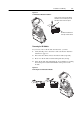
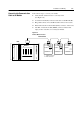
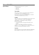
Figure 3.7
Remote Bus Connection
Master Interfaces:
InterBus
Master
PLC
Remote Bus
InterBus
SSC160-C
InterBus
SSC160-C
InterBus
SSC160-C
m
f: female connector
m: male connector
mm
f
ff