
Manual


3–6 Installation and Wiring
Wiring the Connectors
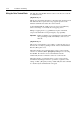
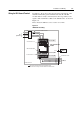
The example in Figure 3.7 can be used as a guide when wiring.
Important: Keep communication wiring away from high noise
sources such as motor cables.
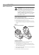
Figure 3.5
Wiring the IB1 Connectors
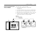
Note: For better visibility of the status LED's it is recommended to
use a cable inline with connector (180° not 90°).
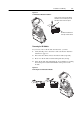
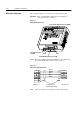
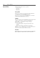
Figure 3.6
Remote Bus Cable Termination
Male end via strain relief Female end
(Grounding Clamp)
Note: Wire colors may vary depending on cable manufacturer
9-Pin, Male D-Shell Connector (IN)
Pin 1
Pin 9
9-Pin, Female D-Shell Connector (NEXT)
Ground Connection
Terminal
/DO 6
DO 1
/DI 7
DI 2
COM 3
9
5
6 /DO
1 DO
7 /DI
2 DI
3 COM
green
yellow
pink
gray
brown