
Manual


Installation and Wiring 3–5
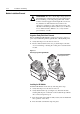
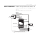
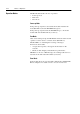
Wiring the IB1 Ground Terminal
In addition to the ground connections shown in Appendix C of the
160 SSC manual, the ground terminal at the bottom of the IB1
module must be solidly connected (and as short as possible) to the
signal common terminal 3 at TB3 of the 160 SSC drive, as shown in
Figure 3.4:
This connection shall have a cross section of 1.5 mm
2
.
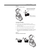
Figure 3.4
IB1 Module Grounding
R/L1
S/L2
T/L3
PE
AC
nput Line
Shielded Enclosure
Enclosure Ground Connection
U/T1
Shielded Motor Cable
to TB3
Control
Cabinet
➊
to Motor
V/T2
W/T3
T (L3)
S (L2)
R (L1)
= EMC Tested Shielded Cable Clamp (or Metal Conduit)
➊
When the control circuitry is located outside of the 160 enclosure.
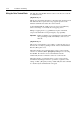
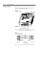
Control Wiring TB3
Motor Wiring TB2
Ground Terminal – PE
Line Power TB1
Line
Filter
DC+
W/T3
1
3
45678910112
V/T2
U/T1
DC–
BR+
T/L3
S/L2
R/L1
BR–
FAULT
READY
Ground Terminal – PE
IB1 Communication
Module
IB1 Ground Terminal