60-IB1 InterBus Communication Module Catalog Number: 160-IB1 Firmware: 1.
Important User Information Solid state equipment has operational characteristics differing from those of electromechanical equipment. “Safety Guidelines for the Application, Installation and Maintenance of Solid State Controls” (Publication SGI-1.1) describes some important differences between solid state equipment and hard-wired electromechanical devices.
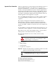
Table of Contents Preface Using This Manual Who Should Use This Manual? . . . . . . . . . . . . . . . . . . . . . . . . . . . . . . . . . Conventions . . . . . . . . . . . . . . . . . . . . . . . . . . . . . . . . . . . . . . . . . . . . . . . . IB1 Compatibility . . . . . . . . . . . . . . . . . . . . . . . . . . . . . . . . . . . . . . . . . . . . . Reference Manuals . . . . . . . . . . . . . . . . . . . . . . . . . . . . . . . . . . . . . . . . . . Safety Precautions . . . . . . . . . . . . . . . . . .
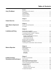
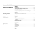
ii Table of Contents Chapter 6 Using the 160-IB1 on InterBus Required Tools . . . . . . . . . . . . . . . . . . . . . . . . . . . . . . . . . . . . . . . . . . . . . . 6-1 Create an InterBus Network Configuration Frame. . . . . . . . . . . . . . . . . . . 6-2 Controlling the Drive with I/O Messaging . . . . . . . . . . . . . . . . . . . . . . . . . . 6-6 The InterBus PCP Telegram. . . . . . . . . . . . . . . . . . . . . . . . . . . . . . . . . . . .
Preface Using This Manual The purpose of this manual is to provide you with the necessary information to apply the Bulletin 160-IB1 Communications Module. Described in this manual are methods for installing, configuring, and troubleshooting the 160-IB1 InterBus Communications Module. For information on specific drive features, refer to the 160 SSC™ Variable Speed Drive (Series C) User Manual.
p–ii Preface Reference Manuals The following documents contain additional information concerning Allen-Bradley products. To obtain a copy, contact your local AllenBradley Sales Office or visit the “On-Line Publications” area of the Allen-Bradley Internet home page at: www.ab.com.
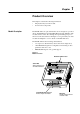
Chapter 1 Product Overview This chapter contains the following information: • The physical layout of the module. • Overview and components. Module Description The IB1 Module is an optional interface device designed to provide a direct, digital link between an InterBus Master and the 160 Drive. The module connects to the drive through the expansion/keypad port on the front of the drive. Refer to the Figure 1.1 for general layout of the module and Chapters 4 or 8 for details on the LED indicators.
1–2 Product Overview End of Chapter 1
Chapter 2 Quick Start for Experienced Users This chapter can help you start using the IB1 Communication Module. If you have installed or configured a network previously and are familiar with Allen-Bradley communication modules and drives, this information can help reduce the time of installation. If you are uncertain, use the full installation/configuration information beginning in Chapter 3.
2–2 Quick Start for Experienced Users Procedures Step Action 1. 2. For Further Information Refer to… Review Attention statements in the Preface. Ensure that power to the 160 Drive has been removed. 3. Verify that the 160 Drive is correctly installed and wired. Stop Input (TB3-7, TB3-8) must be jumpered together to start drive. 4. Configure the 160 Drive for the IB1 Module so the drive can accept control logic and speed reference via the network.
Chapter 3 Installation and Wiring This chapter contains information needed to: • Check for rotational direction to comply with DRIVECOM 20. • Meet the requirements of the EMC and LowVoltage directives for CE compliance. • Remove a pre-installed Program Keypad Module or Ready/Fault Indicating Panel. • Install the IB1 Module. • Wire the communication cables. • Wire the protection earth connection • Remove the IB1 Module from the drive.
3–2 Installation and Wiring Module Installation/Removal ! ATTENTION: The drive contains high voltage capacitors which take time to discharge after removal of mains supply. Before installing or removing a keypad/module, ensure isolation of mains supply from line inputs R, S, T (L1, L2, L3). Wait the recommended amount of time for the capacitors to discharge to safe voltage levels (refer to the 160 SSC™ Variable Speed Drive (Series C) User Manual for recommended time).
Installation and Wiring 3–3 Figure 3.2 Communication Module Installation Latch must be in this position before installation. Once installed, push the latch down until it locks into place. Module should be flush with top surface of drive Removing the IB1 Module If you need to remove the module from the drive, you must 1. Verify that all power to the drive is removed. Review Attention statement on page 3–2. 2. Disconnect the cable/connector from the module (if present). 3.
3–4 Installation and Wiring Wiring the Drive Terminal Block The 160 drive and 160-IB1 interface can be controlled on a network in 2 different modes. [Input Mode] = 2 This mode is used where the drive is controlled solely by the network. The 160-SSC drive requires, that a stop signal is present on the hardware terminals, before the drive can be started. Control Terminal Block 3 (TB-3) pins 7 & 8 need to be linked by ether a wire bridge or a normally closed stopping device. Fitting a stopping device (e.g.
Installation and Wiring Wiring the IB1 Ground Terminal In addition to the ground connections shown in Appendix C of the 160 SSC manual, the ground terminal at the bottom of the IB1 module must be solidly connected (and as short as possible) to the signal common terminal 3 at TB3 of the 160 SSC drive, as shown in Figure 3.4: This connection shall have a cross section of 1.5 mm 2 . Figure 3.
3–6 Installation and Wiring Wiring the Connectors The example in Figure 3.7 can be used as a guide when wiring. Important: Keep communication wiring away from high noise sources such as motor cables. Figure 3.5 Wiring the IB1 Connectors 9-Pin, Female D-Shell Connector (NEXT) Ground Connection Terminal Pin 9 Pin 1 9-Pin, Male D-Shell Connector (IN) Note: For better visibility of the status LED's it is recommended to use a cable inline with connector (180° not 90°). Figure 3.
Installation and Wiring Connecting the Communication Cable to the Module 3–7 Follow these steps to connect your module. 1. Verify that the cable/connector is correctly wired (See Figure 3.6). 2. Locate the D-shell (IN) connector at the base of the IB1 Module. 3. Plug cable/connector into the IB1 D-shell connector and secure. 4. Extend the network via the D-shell (NEXT) connector on the front. 5. Last IB1 of network, D-shell (NEXT) connector must be left empty for the network to be correctly terminated.
3–8 Installation and Wiring End of Chapter 3
Chapter 4 Modes of Operation Chapter 4 contains the following information: • Powering up the drive with the IB1 Module installed. • The modes of operation and LED indications. Powering Up the Drive After you have installed the IB1 Module, apply power to the drive and to the connected device. The READY LED should illuminate. If it does not, refer to Chapter 8, Troubleshooting. LED Indicators The IB1 Module has five LEDs (see figure below) which provide module status.
4–2 Modes of Operation Operation Modes The IB1 Module has three modes of operation. • Power-up mode • Run mode • Error mode Power-up Mode If the power-up sequence is successful, the module enters the run mode (RC LED on) and the TR LED flashes green. If the power-up sequence fails, the TR LED will go to off and the module will enter the Error Mode (see below). Run Mode After a successful power-up, the IB1 Module enters the run mode and operates as a slave device to a master device (BA LED on).
Chapter 5 InterBus Parameter Descriptions and Data Protocol This chapter provides a listing and description of the Bulletin 160 Drive parameters related to Network Operation, and the IB1 Module Data Protocol information. Important: Refer to your 160 SSC™ Variable Speed Drive (Series C) User Manual for drive parameter descriptions.
5–2 InterBus Parameter Descriptions and Data Protocol InterBus Data Protocol Data Channels The data transfer in Interbus terminology is called Peripherals Communications Protocol (PCP). Process data and parameter data is transmitted in the InterBus system via two independant transmission channels. i.e. the process data channel and the parameter data channel. The process data channel cyclically transmits process data in the form of an I/O image.
InterBus Parameter Descriptions and Data Protocol Data from IB1 Slave to InterBus Master 5–3 Speed Feedback, displayed by Register 1, is scaled in RPM according to P66 - [RPM Scaling]. Table 5.B Register No. 0 1 2 Control and Status Word DRIVECOM 20/21 Register (Words) Status Word Speed Feedback Diagnostics Description According to DRIVECOM 20 160 Drive Output Frequency (motor RPM) reserved Control and Status word bits are defined as follows (speed control): Table 5.
5–4 InterBus Parameter Descriptions and Data Protocol Drive State Transitions The following Figure 5.1 shows the most important state transitions Figure 5.1 State Diagram DRIVE FAULT 00x1'1000 1 15 SWITCH ON DISABLED Reset fault 0xxx xxxx to 1xxx xxxx (Power-up and diagnostics o.k.
InterBus Parameter Descriptions and Data Protocol Parameter Access 5–5 Parameter access is established by object indices and parameter related sub-indices to be sent via the PCP telegram. Table 5.
5–6 InterBus Parameter Descriptions and Data Protocol Communication Statistics The following communication statistics can be read via the InterBus Register 3 from the Network option. Table 5.
Chapter 6 Using the 160-IB1 on InterBus The purpose of this chapter is to provide an example of the steps necessary to use the 160-IB1 on an InterBus network. As InterBus is a 3rd party network, we will be using an SST-IBS-SLC scanner to act as a master for InterBus, residing in an A-B SLC500 rack. The SST scanner sends I/O messages periodically to a Bulletin 160-IB1 to start and stop the drive and control its speed.
6–2 Using the 160-IB1 on InterBus Create an InterBus Network Configuration Frame This example assumes that the SLC 500 rack has been configured correctly with the SST-IBS-SLC card in slot 3. If configuration is required an example of configuration is shown further in this chapter – The InterBus PCP Telegram. Additionally it is assumed that a 160 drive with an 160-IB1 interface is connected on the InterBus remote bus with a relevant 9 way D shell connector (see chapter 3).
Using the 160-IB1 on InterBus 6–3 Click (select) the controller board and right mouse click ”type” to select the type of scanner. Click IBS USC(4K) as the controller type and click ok. With the ”controller board” selected, hit F3 on your PC (the state button). Select Configuration (on-line) and click ok. If the processor is faulted, you will not be able to go on-line. So put the processor into program mode with the keyswitch., then select Configuration (on-line).
6–4 Using the 160-IB1 on InterBus . Look at the LED’s on the 160-IB1 module, BA is flashing, indicating that the module is not being controlled by anything. Now with the controller still selected, right click and choose ”Parameterization” and ”Edit” to specify how we want the scanner to start up. Select ”Startup without PDP” and uncheck ”start data transmission” (action 23) and click ok.
Using the 160-IB1 on InterBus 6–5 Now save the file with a filename. Choose ”File” and ”Save” commands. The network should now be configured with the 160-IB1 BA LED now steady green. If not, check that the processor is in Run mode. InterBus assigns a communication reference (CR) dynamically when the network(frame) is read in. It starts with the first module it sees on the network, assigns a CR=2 and specifies memory allocation for the I/O messaging.
6–6 Using the 160-IB1 on InterBus Controlling the Drive with I/O Messaging Now adjust the drive parameters as defined in chapter 5 of this manual in order to test the drive with the following program example: Figure 6.1 Drive Test Program Ladder Logic Example.
Using the 160-IB1 on InterBus Drive Test Program Ladder Logic Example (continued) 6–7
6–8 Using the 160-IB1 on InterBus The InterBus PCP Telegram The Peripherals Communication Protocol (PCP) of InterBus supports 2 different types of independent data transmission. The 3 words that were mapped previously in this chapter, is the process data channel which is the cyclic transmitted I/O data to start/ stop the drive and provide reference and feedback. The parameter data channel is much slower, working around the process data channel, to read/write parameters to the drive.
Using the 160-IB1 on InterBus 6–9 Select the Advanced Config button, to setup the card as shown. This means that there are 32 words reserved for process data (I/O) and the M files are set to 384 words. To make PCP function we need to setup the G files with data . So the G files length = 7. Select the Edit G file data button, to setup the data for the InterBus telegram.
6–10 Using the 160-IB1 on InterBus This is an example of a read drive parameter (all values in hex) The first node on the network is a communication reference (CR) = 2, with the parameter read access index of 5FF0 (see table 5E) and the sub-index specifying parameter 8 [Heatsink Temperature].
Using the 160-IB1 on InterBus Reading and Configuring Parameters with the PCP Telegram 6–11 Figure 6.2 PCP Telegram Ladder Logic Example This program example can be made to operate by first setting I:1.4 to request a read or write operation, the setting B3:20 bit 0 to 1 to update the data in N7:70 onwards into the M0 files, then setting B3:20 bit 1 to 1 to send the data.
6–12 Using the 160-IB1 on InterBus PCP Telegram Ladder Logic Example (continued)
Chapter 7 Controlling the Drive Controlling the 160 Drive from a programmable controller is accomplished using Message Commands to communicate through the IB1 Module to the drive. To send a Start or Stop command to the drive, the corresponding control bits in the DRIVECOM Control Word must be set. Setting the Drive to Enable Network Control The 160 Drive must be configured to accept logic and speed commands from the network. This is done by configuring three parameters: 1.
7–2 Controlling the Drive End of Chapter 7
Chapter 8 Troubleshooting The purpose of this chapter is to help you troubleshoot your IB1 Module. ! ! ATTENTION: Servicing energized industrial control equipment can be hazardous. Electrical shock, burns, or unintentional actuation of controlled industrial equipment may cause death or serious injury. Follow the safety-related practices of NPFA 70E, Electrical Safety for Employee Workplaces, when working on or near energized equipment. Do not work alone on energized equipment.
8–2 Troubleshooting Communication Status LEDs In case no LED is on, check the options connected to the SSC160. The four Communication Status LEDs provide status information on module operations. Table 8.A shows how to use the LED to detect and correct common operating problems. Table 8.
Troubleshooting Fault No. [Hex] 7510 7520 8100 8311 8313 Fault Name 8–3 Fault Code SSC160 [Dec] Serial interface to drive timeout Serial interface IBS bus not active Monitoring: Communication Monitoring/ Torque Control: Excess Torque Monitoring/ Torque Control: Standstill Torque 36 7 6 Drive faults can be read via index 0x603F. Refer to Table 8.C Table 8.D for fault number relation. Drive fault codes can be read by accessing drive parameter P07 - [Last Fault]. Refer to Table 8.C and Table 8.
8–4 Troubleshooting IB1 Network Error Codes The following error codes could be returned when accessing the IB1 Module. Table 8.D Network Fault Codes Fault Code 7510 Serial Fault Fault Indication Description No serial Connection established 7520 7500 5000 Unit lost Connection Unit unrecoverable Fault Model of Drive not valid Timeout on serial link Unexpected Network Fault Use 160 Drive with version ’C’ or higher Corrective Action Check if SSC160 of version ‘C’ or higher has been installed.
Appendix A Specifications Electrical Supply Voltage Power Consumption Environmental Ambient Temperature Operating Storage Relative Humidity Vibration Supplied by Drive 1.4 Watts (280 mA) maximum Altitude 0 to 65° C (32 to 149° F) –40 to 85° C (–40 to 185° F) 0 to 95% non-condensing 1.0 G Operational 2.0 G Non-operational 15.0 G Operational 30.0 G Non-operational 1,000 m (3,300 ft.
A–2 Specifications End of Appendix A
Index B Baud Rate, A–1 C Cabling, 3–6 CE Compliance, 3–1 Communication Cable, 3–7 Communication Statistics, 5–6 Configuration Parameters , 6–11 SST-IBS-SLC, 6–8 Control Word, 5–3 Controlling, Drive , 6–6, 7–1 D Data Channels , 5–2 Data Protocol , 5–2 Dimensions, A–1 E Error Mode , 4–2 F Fault Codes Drive, 8–3 Network , 8–4 Parameter Access, 5–5 I I/O Messaging, 6–6 Installation, 3–1 InterBus Network Configuration Frame, 6–2 Error Codes , 8–4 K Keypad Removal , 3–2 L Ladder Logic Example PCP Telegram
Index–2 State Transitions, 5–4 Status Word, 5–3 T Troubleshooting, 8–1 W Web Sites, p–ii Wiring Connectors, 3–6 Drive Terminal Block, 3–4 Ground Terminal, 3–5
Publication 160IB1-UM010A-EN – October, 2001 P/N 899.02.91 Copyright © 2001 Rockwell Automation. All rights reserved. Printed in Switzerland.