609 Industrial Uninterruptible Power Supply User Manual Installation and Operation 41063-222-01 (1) 990-1868 12/2004
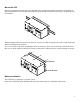
Mount the UPS This unit is designed to mount on a heavy duty DIN rail or on the back panel of an enclosure. For details on DIN rail installation refer to the DIN rail installation guide included in the DIN rail package. The DIN rail kit is not included. When mounting on the back panel of an enclosure, select screws that are appropriate for the weight of this unit and the mounting surface material. Six screws must be used when mounting this unit in an enclosure.
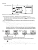
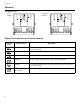
Front Panel 120 V model depicted. 8 7 6 5 4 3 2 1 NO ON CO M BATTERY NC NO LOW CO M BATTERY NC EPO CO M EPO Test PUSH TO RESET INPUT OUTPUT 208/220-240V~ 50/60Hz, 7A MAX GROUND NEUTRAL N 23 0V~ 50/60Hz, 500VA 325W, 2.7A MAX LINE GROUND NEUTRAL N L LINE L Connect Power and Equipment to the UPS Hardwiring should be performed by a qualified electrician. Use appropriate size wires. 1. The UPS features a transient voltage surge-suppression (TVSS) screw located on the front panel.
Connectors Communication Port A standard serial interface cable is incompatible with the UPS. Use the cable supplied with the unit. SERIAL PORT Contact Closure Port 8 7 6 5 4 3 2 1 The relays are connected from the common (COM) to the normally closed (NC) pins.When the unit enters a low battery or on battery state, the appropriate relay will transition and connect the common (COM) to the normally open (NO) pin.
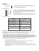
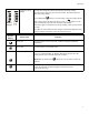
Operation Operation UPS Display Panel 120 V models INPUT 208/220-240V~ 50/60Hz, 7A MAX GROUND 208/230 V models Test NEUTRAL N LINE L OUTPUT 230V~ 50/60Hz, 500VA 325W, 2.7A MAX GROUND NEUTRAL N Test INPUT OUTPUT 208/220-240V~ 50/60Hz, 7A MAX 230V~ 50/60Hz, 500VA 325W, 2.7A MAX L2/N L2/N LINE L L1 L1 Display Panel Indicators and Function Buttons Indicator LED Indicator Title Description On-Line The UPS is supplying utility power to the connected equipment (see Troubleshooting).
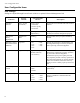
Operation Diagnostic Utility Voltage The UPS has a diagnostic feature that indicates the utility voltage. The UPS starts a self-test as part of this procedure. The self-test does not affect the voltage display. Press and hold the After a few seconds, this five-LED Battery Charge indicator on the right of the display panel will show the utility input voltage. Refer to the figure on the left for the voltage reading (values are not listed on the UPS).
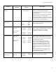
User Configurable Items User Configurable Items UPS settings Settings are adjusted through PowerChute software or optional Network Management Card. Function 8 Factory Default User Selectable Choices Description Automatic Self-Test Every 14 days (336 hours) • Every 7 days (168 hours) • On start up only • No self-test Set the interval at which the UPS will execute a self-test. UPS ID UPS_IDEN Up to eight characters (alphanumeric) Uniquely identify the UPS (i.e.
User Configurable Items Function Factory Default User Selectable Choices Description Low Battery Warning 2 minutes 2, 5, 8, 11, 14, 17, 20, 23 minutes PowerChute software interface provides automatic, unattended shutdown when approximately two minutes of battery operated run time remains. The low-battery warning beeps are continuous when two minutes of run time remain.
Storage, Maintenance, Transport Storage, Maintenance, Transport Storage Store the UPS covered in a cool, dry location with the batteries fully charged. At 5° to 86° F (–15° to 30° C), charge the UPS battery every six months. At 86° to 113° F (30° to 45° C), charge the UPS battery every three months. Replacing the Battery Module This UPS has an easy-to-replace, hot-swappable battery module. Replacement is a safe procedure, isolated from electrical hazards.
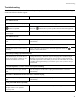
Troubleshooting Troubleshooting Use this chart to solve minor installation and operation problems. Refer to Rockwell Automation Tech Support at 440-646-5800 for further support. Problem and/or Possible Cause Solution UPS will not turn on The battery is not connected properly. button not pushed. The UPS is not connected to utility power supply. Check that the battery connector is fully engaged. Press the button once to power-up the UPS and connected equipment.
Troubleshooting Problem and/or Possible Cause Solution All LEDs are off and the UPS is wired to input utility power The UPS is shut down or the battery is discharged from an extended outage. None: The UPS will restart automatically when utility power is restored and the battery has a sufficient charge. The Overload LED is illuminated and the UPS emits a sustained alarm tone The UPS is overloaded.
Troubleshooting Problem and/or Possible Cause Solution There is no utility power There is no utility power and the UPS is off Use the cold start feature to supply power to the connected equipment from the UPS battery(s). Press and hold the button. The unit will emit two beeps, one short beep and one long beep. Release the button during the second beep. UPS operates on battery although line voltage exists The UPS input circuit breaker trips. Unplug all nonessential equipment from the UPS.
Service and Contact Information Service and Contact Information Service If the UPS requires service do not return it to the dealer. Follow these steps: 1. Review the problems discussed in Troubleshooting to eliminate common problems. 2. If the problem persists, contact Rockwell Automation Customer Support. – If the product is determined to be defective, contact the distributor for typical return procedures. – Retain the battery and the Network Management Card (when available). 3.
Safety Information - SAVE THIS GUIDE This Safety Guide contains important instructions that should be followed during installation and maintenance of the equipment and batteries. It is intended for customers who setup, install, relocate, or maintain equipment. Changes and modifications to this unit not expressly approved could void the warranty.