Allen-Bradley User Manual for 350 VA Industrial UPS 1609-S350NS - 350 VA, 120 V 1609-S350ES - 350 VA, 208/230 V Installation and Operation 41063-287-01 (1) 990-2954 05/2006
Installation Installation Mounting the UPS This unit is designed to mount on the back panel of an enclosure. An optional Din rail mounting kit, 1609SDK1, is also available. When mounting on the back panel of an enclosure, select screws that are appropriate for the weight of this unit and the mounting surface material. Six screws must be used when mounting this unit in an enclosure. Three screws in the top of the bracket and three screws in the bottom of the bracket.
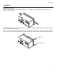
Installation Connecting the Battery Remove the Battery Door, Connect the Battery, and Reinstall the Battery Door Hardwiring Wiring of the UPS should be performed by a qualified electrican using appropriate wire gauges. Connecting Power and Equipment to the UPS Front Panel (120 V model shown): Test PUSH TO RESET INPUT 208/220-240V~ 50/60Hz , 7A MAX GROUND NEUTRAL N 4 LINE L OUTPUT 230V~ 50/60H z, 500VA 325W, 2.
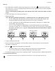
Installation Start-Up 1. The UPS features a transient voltage surge-suppression (TVSS) screw located on the front panel. The TVSS screw is used for connecting the ground lead on surge suppression devices such as telephone and network line protectors. Prior to connecting the grounding cable, ensure that the UPS is NOT connected to utility or battery power. 2. Connect the battery (see Connecting the Battery). 3. Hardwire the UPS. Note: Hardwiring should be performed by a qualified electrician.
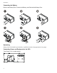
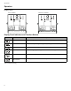
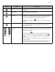
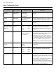
Operation Operation Display Panel 120 V models 208/230 V models Test Test INPUT OUTPUT 208/220-240V~ 50/60Hz, 7A MAX GROUND NEUTRAL N INPUT 230V~ 50/60Hz, 500VA 325W, 2.7A MAX LINE GROUND NEUTRAL N L OUTPUT 208/220-240V~ 50/60Hz, 7A MAX 230V~ 50/60Hz, 500VA 325W, 2.7A MAX L2/N L2/N LINE L L1 L1 Display Panel Indicators and Function Buttons Indicator Title Description On-Line The UPS is supplying utility power to the connected equipment.
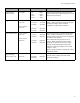
Operation Feature Function Description Power On Press this button to turn on the UPS. Read on for additional capabilities. Power Off Press this button to turn off the UPS. Self-Test Automatic: The UPS performs a self-test automatically when turned on, and every two weeks thereafter (by default). During the self-test, the UPS briefly operates the connected equipment on battery. Manual: Press and hold the self-test.
User Configurable Items User Configurable Items Settings are adjusted through PowerChute software or optional network management card. Function 8 Factory Default User Selectable Choices Automatic Self-Test Every 14 days (336 hours) • Every 7 days (168 hours) • On start-up only • No self-test Set the interval at which the UPS will execute a self-test. UPS ID UPS_IDEN Up to eight characters (alphanumeric) Uniquely identify the UPS (i.e. server name or location) for network management purposes.
User Configurable Items Function Factory Default User Selectable Choices Synchronized Turn-on Delay 0 seconds • • • • High Transfer Point 120 V models: 127 VAC 230 V models: 253 VAC Low Transfer Point 120 V models: 106 VAC 230 V models: 208 VAC Output Voltage 230 V models only 230 VAC 0s 60 s 120 s 180 s • • • • 240 s 300 s 360 s 420 s Description Specify the time the UPS will wait after the return of utility power before start-up (to avoid branch circuit overload).
Storage, Maintenance, Transport Storage, Maintenance, Transport Storage Store the UPS covered in a cool, dry location with the battery module(s) fully charged. At 5° to 86° F (–15° to 30° C), charge the UPS battery module every six months. At 86° to 113° F (30° to 45° C), charge the UPS battery module every three months. Replacing the Battery Module This UPS has an easy-to-replace, hot-swappable battery module. Replacement is a safe procedure, isolated from electrical hazards.
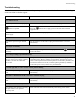
Troubleshooting Troubleshooting Use this chart to solve minor installation and operation problems. Refer to Rockwell Automation Tech Support at 440-646-5800 for further support. Problem and/or Possible Cause Solution UPS will not turn on The battery is not connected properly. button not pushed. The UPS is not connected to utility power supply. Check that the battery module connector is fully engaged. Press the equipment.
Troubleshooting Problem and/or Possible Cause Solution All LEDs are off and the UPS is wired to input utility power The UPS is shut down or the battery module is discharged from an extended outage. None. The UPS will restart automatically when utility power is restored and the battery module has a sufficient charge. The overload LED is illuminated and the UPS emits a sustained alarm tone The UPS is overloaded.
Troubleshooting Problem and/or Possible Cause Solution There is no utility power There is no utility power and the UPS is off. Use the cold start feature to supply power to the connected equipment from the UPS battery module(s). Press and hold the button. The unit will emit two beeps, one short beep and one long beep. Release the button during the second beep. UPS operates on battery although line voltage exists The UPS input circuit breaker trips. Unplug all nonessential equipment from the UPS.
Service and Contact Information Service and Contact Information Service If the UPS requires service do not return it to the dealer. Follow these steps: 1. Review the problems discussed in Troubleshooting to eliminate common problems. 2. If the problem persists, contact Rockwell Automation Customer Support. • If the product is determined to be defective, contact the distributor for typical return procedures. • Retain the battery module. 3. Pack the UPS in its original packaging.