Quick Start Bulletin 1609 UPS Ethernet Network Card 1609-ENET
Important User Information Read this document and the documents listed in the additional resources section about installation, configuration, and operation of this equipment before you install, configure, operate, or maintain this product. Users are required to familiarize themselves with installation and wiring instructions in addition to requirements of all applicable codes, laws, and standards.
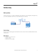
Preface Overview The 1609 Network Management Card is a device that can provide an interface between an Uninterruptible Power Supply (UPS) and a network. It not only can communicate with a UPS and acquire its information, but it's also able to remotely manage a UPS through a network system. This 1609-ENET card can support two kinds of protocols - SNMP and HTTP for user access.
Preface Notes: 4 Rockwell Automation Publication 1609-QS002A-EN-P - May 2014
Table of Contents Important User Information . . . . . . . . . . . . . . . . . . . . . . . . . . . . . . . . . . . . . . . 2 Preface Overview /Additional Resources . . . . . . . . . . . . . . . . . . . . . . . . . . . . . . . . . . . . 3 Chapter 1 Web Mode Setup . . . . . . . . . . . . . . . . . . . . . . . . . . . . . . . . . . . . . . . . . . . . . . . . . . 7 Chapter 2 Ethernet Mode Setup. . . . . . . . . . . . . . . . . . . . . . . . . . . . . . . . . . . . . . . . . . . . . .
Table of Contents Notes: Rockwell Automation Publication 1609-QS002A-EN-P - May 2014 6
Chapter 1 Web Mode Setup Web Server Mode This chapter will allow you to configure the UPS ENET card for the Web Server mode. It will guide you through the setup process of the 1609-ENET card in order to access the UPS information via web browser. Before You Begin Review the 1609 Network Management Card installation instruction and user manuals.
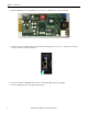
Chapter 2 Web Mode Setup 1. Flip all 4 DIP switches to the DOWN position in order to enable Web Server mode on the card. 2. Check that both of the DIP switches of the 1609 Network Management Card are set to 'OFF' position (normal mode) to enable the network transmission. 3. Insert the card in the UPS ENET card slot. Note: This 1609-ENET card is hot swappable 4. Connect the Ethernet cable to the bottom Ethernet port.
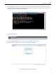
Web Mode Setup Chapter 2 5. Use the PING utility to check the connection between your PC and the ENET card. From Windows, launch the Command Prompt and enter ping 192.168.1.100. You should receive replies. Note: Make sure your computer is on the same network as the UPS with a static IP address. 6. Launch your web browser. 7. Type the 1609-ENET IP address “192.168.1.100” in the address bar and press enter. 8. Type the username and password.
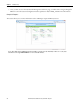
Chapter 2 Web Mode Setup 9. Once you have access to the 1609 Network Management Card home page, you will be able to navigate through the different sections for status and configuration. Refer to publication 1609-UM009_-EN-P for more information. Example: UPS Properties This section allows you to monitor information such as UPS Input, Output and Battery statuses.
Chapter 2 Ethernet Mode Setup This chapter will guide you through the configuration process of the 1609- ENET card to properly communicate with a ControlLogix controller and an Ethernet bridge. You will be using RSLinx Classic and RSLogix5000 software. Before You Begin Review the 1609 Network Management Card installation instruction and user manuals.
Chapter 2 Ethernet Mode Setup 1. 1.Flip DIP switch number one to the UP position in order to enable Ethernet mode on the card. 2. Check that both of the DIP switches of the 1609 Network Management Card are set to 'OFF' position (normal mode) to enable the network transmission. 3. Insert the card in the UPS ENET card slot. Note: This 1609-ENET card is hot swappable 4. Ensure you connect the Ethernet cable to the bottom Ethernet port.
Ethernet Mode Setup Chapter 2 5. Use the PING utility to check the connection between your PC and the ENET card. From Windows, launch the Command Prompt and enter ping 192.168.1.100. You should receive replies. Note: Make sure your computer is on the same network as the UPS with a static IP address. 6. Open RSLinx Classic and create an Ethernet driver. Go to the Communications toolbox and select Configure Drivers.
Chapter 2 Ethernet Mode Setup 7. Select Ethernet devices from the drop down menu and select Add New. 8. Enter the respective IP addresses of your devices and select OK.
Ethernet Mode Setup Chapter 2 9. Ensure that you can see the 1609-ENET card. The device should appear as follows: Program Setup 1. In your RSLogix5000 program, add an "ETHERNET-MODULE" under the Ethernet Network Bridge in the IO Configuration tree.
Chapter 2 Ethernet Mode Setup 2. Make sure you have the correct parameters including the Comm Format and IP address (192.168.1.100). Select OK. Note: If you are online you'll be prompted with an "Online Module Creation" warning message; check the "Inhibit Module Connection" and select YES.
Ethernet Mode Setup Chapter 2 3. Go to the Generic Ethernet module properties. 4. Go the Connection tab. Change the RPI to 1000ms, uncheck the "Inhibit Module" and select OK.
Chapter 2 Ethernet Mode Setup Note: If you are online you'll be prompted with an "Uninhibiting Module Online" warning, select Yes. 5. After adding your module with the correct parameter, you should have an "IO Not Responding" and a yellow triangle in your module.
Ethernet Mode Setup Chapter 2 6. Go to the "Controller Scope Tags" and identify your UPS ENET card input/output/configuration tags. Change the "XXXX:C.Data[0].0" tag from 0 to 1. Note: XXXX is a unique name given to the UPS ENET card. ENET_Card was the name given in this example, therefore the full tag name is "ENET_Card:C.Data[0].0" 7. Reset the card by pressing the black circle button on the card. Wait approximately 45 seconds until communications are established.
Chapter 2 Ethernet Mode Setup Explicit Message Example: Follow these steps to configure an explicit message in order to retrieve the UPS output rating information. 1. Create a new "User-Defined Data Type" called "Output Rating". 2. Go to the "Controller Tags" and create a new tag called "UPS" with an "Output Rating" data type. 3. Add a new message instruction in your routine with the following parameters. Select OK once you enter all the required parameters.
Ethernet Mode Setup Rockwell Automation Publication 1609-QS002A-EN-P - May 2014 Chapter 2 21
Chapter 2 Ethernet Mode Setup 4. Finalize all edits in the program. Go to the "Controller Tags", you should be able to see your results.
Appendix A EtherNet/IP Object Service Appendix A –EtherNet/IP Object Service EtherNet/IP is an object orientated protocol. The Object Oriented structure therefore allows for classes, instances, attributes and services. The ‘data types’ listed below are to be considered as the objects supported in the protocol. Each of these has attributes that have been supported to differing degrees.
Appendix A EtherNet/IP Object Service Return Code Name Description 0x00 0x0F 0x08 Success Privilege violation Service not supported Service was successfully performed by the object specified. A permission/privilege check failed The requested service was not implemented or was not defined for this Object Class/Instance. 0x01 Connection failure A connection related service failed along the connection path.
Appendix B EtherNet/IP Parameters Appendix B – EtherNet/IP Parameters Identity Object (0x01) Attribute ID Rule 1 Get Name Vendor ID Data Type UINT 2 3 Get Get Device Type Product Code UINT UINT 4 Get Revision STRUCT of Get Get Get Get Major Minor Status Serial Number Product Name State USINT USINT WORD UDINT SHORT_STRING USINT 5 6 7 8 TCP/IP Interface Object (0xF5) Attribute ID Rule Name 1 Get Status 2 Get Configuration Capability 3 Set Configuration Control 4 Get Physical Link Object Path
Appendix B EtherNet/IP Parameters UPS Object (0x377) Attribute ID Need Access Rule 1 Required Get 2 Required Get 3 Required 4 NV NV NV NV NV NV NV NV Name Output Rating VA Voltage Frequency Input Rating Voltage Frequency Data Type STRUCT of: INT INT INT STRUCT of: INT INT Get NV RatingBatteryVoltage INT Get NV LowTransferVoltage STRUCT of: NV UpBound INT NV LowBound INT NV HighTransferVoltage Array of STRUCT of: NV UpBound INT NV LowBound INT Required Get 5 6 Requir
Appendix B UPS Object (0x377) Attribute ID Need Required Access Rule Get NV V 19 Name Input Line Value Data Type STRUCT of: Frequency INT Voltage 1 INT Description of Attribute Semantics of value The current input values for up to InputNumLines Line frequency to the UPS system in 1/10 Hz Line voltage of the UPS system in 1/10 V normal(0), battery(1), The present source of output power.
Appendix B EtherNet/IP Parameters UPS Object (0x377) Attribute ID Need 32 33 28 Required Required Access Rule NV Name Data Type Get V TestResultsSummary INT Get V Alarm Disconnect PowerFail BatteryLow DWORD bit 0 bit 1 bit 2 LoadWarning bit 3 TestInProgress BatteryTestFail OutputOverload InverterAbnormal ReserveAbnormal OverTemperature OutputBad UPSOff ChargerFail FanFail bit 4 bit 5 bit 6 bit 7 bit 8 bit 9 bit 10 bit 11 bit 12 bit 13 OutputOff bit 14 SmartShutdown bit 15 UPSShut
Appendix C EtherNet/IP IO Data Mapping Appendix C - EtherNet/IP IO Data Mapping If you want to control the UPS device just over the UDP (I/O Connection) Interface, it is sufficient to use the mapping described. This section describes the mapping. The different mappings over different instances are selected in the assembly class.
Appendix C EtherNet/IP IO Data Mapping Produced (Input) Assembly (Instance 0x66) Instance 0x66 describes another input (produced) assembly for the 1609-UPS. Byte 0 1 2 3 Bit 7 4 Reserved 5 Bit 6 Instance 0x66 – Produced (Input) Assembly Bit 5 Bit 4 Bit 3 8 9 10 11 12 13 14 15 16 17 18 19 20 21 22 23 24 25 26 27 30 Bit 1 Bit 0 Reserved for Logix (Logix sets to 0xffff whenever the connection is not established. UPS sets to 0x0000.
Rockwell Automation Support Rockwell Automation provides technical information on the Web to assist you in using its products. At http://www.rockwellautomation.com/support you can find technical and application notes, sample code, and links to software service packs. You can also visit our Support Center at https://rockwellautomation.custhelp.com/ for software updates, support chats and forums, technical information, FAQs, and to sign up for product notification updates.