
User Manual User Manual

Rockwell Automation Publication 1608S-UM001A-EN-P - July 2013 5
Quick Start and Introduction Chapter 1
– Standard Ethernet Cat.-5e cable (Ethernet cross-over cable may be
required for direct connection to older PC Network Interface Cards)
– Phillips-head screwdriver.
– Information from your IT department
(Refer to Ethernet Communications Setup
on page 7)
6. Install the i-Sense according to Installation on page 12
7. Electrical installation must be performed by a qualified electrician or
technician in an appropriate environment (See Technical Specifications on
page 19).
– Choose a communications method: either Ethernet LAN or analog
(PSTN) telephone line.
– Follow the installation instructions
(See Communications Connections on page 15
)
8. Perform step 5, if skipped earlier.
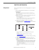
9. Verify communications: push the
♡button to generate a Heartbeat event.
Verify that the event is logged at www.igrid.com.
Introduction
The i-Sense Voltage Sag Detector captures and records voltage disturbances on
the electric power service, as well as long-term voltage trends. Voltage
disturbances are the most common power quality (PQ) problems and may
include voltage sags (dips), swells, or interruptions and outages. Many different
mains voltages are utilized internationally and the i-Sense can be easily
configured to operate with most of them.
The i-Sense detector is an integral part of the i-Grid voltage monitoring network
that enables the reporting and alerting service. Operation of the i-Sense requires
daily communication with the i-Grid servers via the Internet. Instructions for
setting up an Internet connection are included in this Guide.
The latest setup and support information
is available at www.igrid.com.