
User Manual User Manual

Rockwell Automation Publication 1608S-UM001A-EN-P - July 2013 16
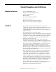
Operation, Maintenance and Troubleshooting Chapter 4
Operation, Maintenance and Troubleshooting
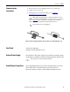
The left-side cover may be removed at any time to access the
communications ports.
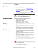
User controls and indicators These user controls and indicators are available:
• The i-Sense Management Console (requires an Ethernet connection
to i-Sense)
• The www.igrid.com website (available from any Web browser)
• Red and Green LED indicators (see Table 3 and Table 4 below)
• RESET push button (located inside left cover)
• Heartbeat
♡ push button (located inside left cover)
LED indicators
The LEDs will flash to indicate status; the flash codes are listed in the tables
below. Additional status information is available by connecting to the i-Sense
Management Console via the Ethernet port.
Startup/Confirmation Blink: At power-up and to confirm a push-button
operation, both LEDs will blink rapidly for a few seconds
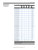
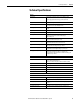
Table 3 - Green NORMAL LED Flash Codes.
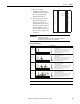
Table 4 - Red ERROR LED Flash Codes.
Flash
Rate
Meaning
Off No Power
1OK
2 Voltage events captured, waiting to transmit.
3 Voltage deviation event detected, voltage has not yet returned to normal (PQ event in progress).
4 Establishing connection to the i-Grid servers.
5 Connected to the i-Grid servers, uploading PQ event data.
Constant Not operating properly. Push RESET button
Flash Rate Meaning/Possible Causes
Off OK
1 Communication error on the last attempt to contact the i-Grid servers. Will retry the connection after a period of time
2 Ethernet interface is not configured and connected to a network
Ethernet interface is initializing
Network cable is unplugged
Note: Only in Ethernet mode
3 Voltage is low. The i-Sense has not detected an AC signal above 90% nominal on each of the enabled voltage channels
4 Both Ethernet and event detection are not initialized yet (combination of status 2 and 3) Note: Only in Ethernet mode