User Manual Bulletin 1608S Voltage Sag Detector Catalog Numbers 1608S-3V480K, 1608S-6V480K
Important User Information Solid-state equipment has operational characteristics differing from those of electromechanical equipment. Safety Guidelines for the Application, Installation and Maintenance of Solid State Controls (publication SGI-1.1 available from your local Rockwell Automation sales office or online at http://www.rockwellautomation.com/literature/) describes some important differences between solid-state equipment and hard-wired electromechanical devices.
Table of Contents Quick Start and Introduction Getting Started . . . . . . . . . . . . . . . . . . . . . . . . . . . . . . . . . . . . . . . . . . . . . . . . . . . . 4 Installation . . . . . . . . . . . . . . . . . . . . . . . . . . . . . . . . . . . . . . . . . . . . . . . . . . . . . . . . 5 Introduction . . . . . . . . . . . . . . . . . . . . . . . . . . . . . . . . . . . . . . . . . . . . . . . . . . . . . . 5 Configuration Configure for your Nominal Voltage . . . . . . . . . . . . . . . . . . . . .
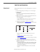
Quick Start and Introduction Chapter 1 Quick Start and Introduction Getting Started Before you begin installation of your i-Sense® Voltage Sag Detector, complete the steps below. 1. Inspect for shipping damage. If any damage is seen, contact the shipper. 2. Record the i-Sense Serial Number: ___________ - ___________ - ___________ The S/N label is located on the bottom of the unit; it will be needed to register/use this i-Sense. 3.
Quick Start and Introduction Chapter 1 – Standard Ethernet Cat.-5e cable (Ethernet cross-over cable may be required for direct connection to older PC Network Interface Cards) – Phillips-head screwdriver. – Information from your IT department (Refer to Ethernet Communications Setup on page 7) 6. Install the i-Sense according to Installation on page 12 7.
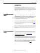
Configuration Chapter 2 Configuration The i-Sense performs simultaneous measurements on three (or six) voltage channels. Typically, these will be the three Line-to-Line (LL) or three Line-toNeutral (LN) voltages of the three-phase AC mains. The i-Sense can also measure single-phase or split single-phase systems. A few settings must be performed to assure safe operation and to properly record the measurements.
Configuration Ethernet Communications Setup Chapter 2 There are several ways to configure the i-Sense for networking. Contact your IT department or System Administrator to discuss the optimal configuration method for your network. Network Security and Firewall Requirements - Ethernet-to-Internet The i-Sense sends measurement data to the i-Grid servers over the Internet on port 80 via the HTTP protocol. The site firewall must allow outbound HTTP traffic from the IP address assigned to the i-Sense.
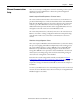
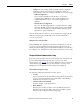
Configuration Chapter 2 Manual Configuration - Ethernet or direct connection to a PC To manually configure the i-Sense with a static IP address: The following network information is needed. When the i-Sense initially powers up, it will attempt DHCP configuration, then default to these values: i-Sense Network Setting Default Value Static IP Address 192.168.1.200 Subnet Mask 255.255.255.0 Default Gateway 192.168.1.1 Primary DNS Server 192.168.1.201 Secondary DNS Server 192.168.1.
Configuration Chapter 2 The i-Sense Management Console Connect to the i-Sense by typing http://192.168.1.200 (replace with the actual IP address) into the Web browser address bar. The i-Sense management console will prompt for a valid username and password. The factory-default user credentials are: Username: admin Password: password Change the username and password from the default values during initial setup. Click on the “Security” menu item to change the default values.
Configuration Chapter 2 • Settings: The “auto-sensing” feature is initially enabled to simplify the configuration process. Auto-sensing can be disabled, in which case selection must be made either to always use DHCP or to use static settings. – DHCP Configuration Select “Obtain an IP address automatically” to use automatic configuration via a DHCP server. To override the DHCP serverassigned DNS addresses, select “Use the following DNS server addresses”.
Configuration Chapter 2 Optional Modem Configuration Settings These optional settings are also available: • Dialing Prefix Set the desired dialing prefix (e.g. if 9 or 8 prefix is needed to access an outside line). The comma (,) character inserts a pause. • Advanced Settings – Blind Dialing If the i-Sense reports that it cannot find a dial-tone even though the line has been tested, it is possible to enable blind dialing to skip the dialtone detection phase of the dialing process.
Installation Chapter 3 Installation Pre-installation 1. Inspect for shipping damage 2. Record the i-Sense serial number (See Getting Started on page 4 3. Register the i-Sense at www.igrid.com (See Getting Started on page 4) 4. Configure the i-Sense hardware for the service voltage (See Getting Started on page 4) 5. Configure communications software using the Ethernet port.
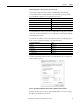
Installation Nominal Voltage Configurations Chapter 3 Table 1 - Nominal Voltage Configurations.
Installation 1. Select your voltage configuration from Table 1 and follow the instructions in the corresponding wiring diagram from Table 2. L e f t 2. Use the appropriate wiring diagram and jumper wire positions. The i-Sense is shipped with jumper wires in the LL configuration. The LL and LN diagrams are also shown inside the i-Sense cover. Move or remove jumper wires as needed.
Installation Communications Connections Chapter 3 1. Remove left side cover (two Phillips-head screws, top and bottom) 2. Conduit entry: top or bottom. 3. Install appropriate communications cable(s) (See Configure Communications Settings on page 6): 8P8C (RJ45) modular Ethernet cable. Pass the Ethernet cable through the included RF filter core, and close the core securely, as shown in Figure 2. Failure to install the cable filter may result in RF emissions beyond the standards of the EU’s EMC Directive.
Operation, Maintenance and Troubleshooting Chapter 4 Operation, Maintenance and Troubleshooting The left-side cover may be removed at any time to access the communications ports. User controls and indicators These user controls and indicators are available: • The i-Sense Management Console (requires an Ethernet connection to i-Sense) • The www.igrid.
Operation, Maintenance and Troubleshooting Chapter 4 Reset Communications If Ethernet port communications fail, the i-Sense has an assigned IP address that may be incompatible with your current LAN. Reset the i-Sense IP address to the default value by simultaneously pressing the RESET and Heartbeat♡ buttons for 10 seconds. This will also reset the security user name and password to their default values. The Ethernet connection will restart after 5 seconds.
Operation, Maintenance and Troubleshooting Chapter 4 • Carefully disconnect the battery plug and pull the battery holder straight out. • Replace or check batteries. Use only the same type rechargeable battery: Nickel-metal-hydride (NiMH), 1.2V AA-size, rated 2000mAh to 3000mAh. Do not use any other battery type. • Important: be sure that battery polarity matches the markings on the battery holder (+ and -) • Replace battery holder straight into the unit. Carefully reconnect he battery plug.
Technical Specifications Chapter 5 Technical Specifications Electrical Nominal Voltage User-selectable, 100V-480Vrms, 1-Phase or 3-Phase Immune to voltage fluctuation up to ±10% of nominal and transient over voltages typically present on mains supply (impulse withstand Category II of IEC 60364-4-443) Frequency 45...65 Hz, auto-sensing Measurement inputs 1 to 3 channels, Cat. No.: 1068S-3V480K (3-channel) Up to 6 channels, Cat. No.: 1068S-6V480K (6-channel) RMS voltage measurement accuracy 0.
Standards Compliance and Certifications Chapter 6 Standards Compliance and Certifications cTUVus (OSHA NRTL) listed Tested to UL and CSA safety standards CE mark (Safety and EMC) RoHS compliant FCC part 68 (Telephone Equipment) FCC part 15 (Emissions) Industry Canada CS-03 (Telephone Equipment) European Union CTR21 (Telephone Equipment) Compliance Information • • • • • • • • FCC PART 68 • This equipment complies with Part 68 of the FCC rules and the requirements adapted by the ACTA.
Standards Compliance and Certifications Chapter 6 • The Telephone Consumer Protection Act of 1991 makes it unlawful for any person to use a computer or other electronic device including fax machines, to send any message unless such message clearly contains in a margin at the top or bottom of each transmitted page or on the first page of transmission, the date and time it was sent and an identification of the business or other entity, or other individual sending the message and the telephone number of the
Standards Compliance and Certifications Chapter 6 • This equipment has been tested and found to comply with the limits for a Class A digital device, pursuant to Part 15 of the FCC Rules. This equipment generates, uses, and can radiate radio-frequency energy. If not installed and used in accordance with the instructions, it can cause harmful interference to radio communications. However, there is no guarantee that interference will not occur in a particular installation.
Rockwell Automation Support Rockwell Automation provides technical information on the Web to assist you in using its products. At http://www.rockwellautomation.com/support, you can find technical manuals, technical and application notes, sample code and links to software service packs, and a MySupport feature that you can customize to make the best use of these tools. You can also visit our Knowledgebase at http://www.rockwellautomation.