
Installation Instructions Owner manual

6 Rockwell Automation Publication 1608S-IN001A-EN-P - July 2013
Bulletin 1608S i-Sense® Installation Instructions
Communications
Connections
1. Remove left side cover (two Phillips-head screws, top and bottom)
2. Conduit entry: top or bottom.
3. Install appropriate communications cable(s)*
* For more information, please refer to Rockwell Automation Publication 1608S-UM001-EN-P
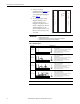
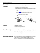
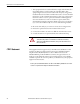
8P8C (RJ45) modular Ethernet cable. Pass the Ethernet cable
through the included RF filter core, and close the core securely, as
shown in Figure 1
. Failure to install the cable filter may result in RF
emissions beyond the standards of the EU’s EMC Directive.
RJ11 telephone line (analog PSTN)
Figure 1 - Ethernet cable filter installation. The clip-on filter core is supplied with the i-sense.
Final Check • Check all connections
• Replace left and right side covers
External Power Supply The external 9V DC power supply (not provided) is used
only during configuration; it should not be used in
normal operation. Remove the left-side cover to access
the 9Vdc jack.
Initial Battery Charge Time The rechargeable batteries may become discharged after some time
on the shelf. Allow 30 minutes charge time after power-up
before the i-Sense is ready to record voltage interruption events.