
Installation Instructions Owner manual

Rockwell Automation Publication 1608S-IN001A-EN-P - July 2013 3
Bulletin 1608S i-Sense® Installation Instructions
Installation
Pre-installation
1. Inspect for shipping damage
2. Record the i-Sense® serial number *
3. Register the i-Sense at www.igrid.com*
4. Configure the i-Sense hardware for the service voltage *
5. Configure communications software using the Ethernet port. (this can be
done after installation and power-up)
* For more information, please refer to Rockwell Automation Publication 1608S-UM001-EN-P
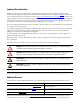
WARNING: Do not apply power to the i-Sense until the wiring is completed
and right-side cover is replaced. Installation must be performed by an
electrician, in accordance with all local and national codes.
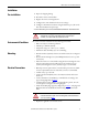
Environmental Conditions
The i-Sense is rated for installation in the following environment:
• Indoor use only, no conductive pollution.
• Altitude up to 2000 m (6500 ft)
• Temperature range +0...+40 °C (+32...+104 °F)
• Maximum relative humidity 95%, non-condensing.
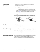
Mounting
• Provide 10 inches (250 mm) clearance around the i-Sense for cooling and
access.
• Remove the left and right covers (four Phillips-head screws, two top and
two bottom)
• Mount the i-Sense to a vertical surface using the four mounting holes. Two
of the four mounting screws should penetrate into studs at least 1 in.
(25mm). Mounting screws 1.5 in. (38mm) long are recommended.
Electrical Connections
• Branch protection: upstream fuse or circuit breaker protection rated 20A
or less is required. Protection rated less than 5 A is not recommended.
• Conduit entry: top or bottom.
• Connect the Ground (Earth) wire to the #10-32 stud near the bottom
knock-out.
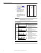
• Connect mains line to the INPUT_1 terminal block, according to the
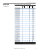
proper wiring diagram from Ta ble 1
.
• 6-Channel Version: if the INPUT_2 terminal block is present, wire the
second 3-phase set using the same wiring diagram.
• Verify that the JP1 plug is properly configured, per Ta ble 2
: The plug with
RED wires must be installed if the channel voltage is greater than 250
VA C.
• Replace the right-side cover and two screws
WARNING: This unit is not rated for 600V AC or 690V AC L-L installations.
600Y/346V installations require 4-wire L-N wiring method. The neutral must be
connected as shown inTable 1
.