
User Manual, 200 A Owner manual


8 Rockwell Automation Publication 1608P-UM003A-EN-P - September 2013
Chapter 2 Installation
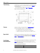
Floor Mounting
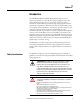
The ProDySC is to be secured to the floor using fasteners and fittings appropriate
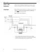
for the type of floor. Holes are provided in the base channels; see Figure 1
for
mounting dimensions.
Note: Top or bottom cable entry is allowed. See Figure 1
and Figure 2 on page 9.
Figure 1 - Bottom View Floor Mount Dimensions
Clearance
ProDySC doors hinge on both right and left. See Figure 26 on page 34 for
dimensions including door swing. Leave required clearances:
• Door swing must allow doors to open at least 90 degrees
• 12” [300mm] clearance on left side and rear for cooling airflow
• 4”[100mm] on right side for air filter clearance when right door opens
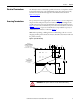
Bypass Switch
Installation of an external maintenance bypass switch is recommended for service
and/or maintenance. Typical switch arrangements are shown in Figure 3 on
page 10 and Figure 4 on page 11. Contact Rockwell Automation for
recommendations and requirements.
Circuit Breaker
Recommendations
Branch circuit protection upstream of the ProDySC is required. Recommended
circuit breakers and maximum allowed circuit breaker ratings are listed in
Tabl e 1
. Branch circuit protection rated less than the ProDySC current rating
may result in nuisance tripping.
Table 1 - Recommended Branch Circuit Protection
ProDySC Rating Max. MCCB Rating
200 A 250 A