User Manual Bulletin 1608P ProDySC Dynamic Voltage Sag Corrector 1608P— 200 Amp Models
Important User Information Solid-state equipment has operational characteristics differing from those of electromechanical equipment. Safety Guidelines for the Application, Installation and Maintenance of Solid State Controls (publication SGI-1.1 available from your local Rockwell Automation sales office or online at http://www.rockwellautomation.com/literature/) describes some important differences between solid-state equipment and hard-wired electromechanical devices.
Table of Contents Important User Information. . . . . . . . . . . . . . . . . . . . . . . . . . . . . . . . . . . . . . . . . . . . . . 2 Additional Resources. . . . . . . . . . . . . . . . . . . . . . . . . . . . . . . . . . . . . . . . . . . . . . . . . . . . . 2 Safety Considerations . . . . . . . . . . . . . . . . . . . . . . . . . . . . . . . . . . . . . . . . . . . . . . . . . . . . 5 Installation Check List . . . . . . . . . . . . . . . . . . . . . . . . . . . . . . . . . . . . . . . . . . . . . . .
Table of Contents Notes: 4 Rockwell Automation Publication 1608P-UM003A-EN-P - September 2013
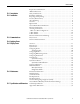
Chapter 1 Introduction The Allen-Bradley Bulletin 1608P ProDySC Dynamic Sag Corrector is engineered to provide years of trouble-free voltage sag (dip) protection. The patented DySC technology does not use batteries, requires only routine maintenance, includes three-stage transient voltage surge suppression, and has unparalleled energy efficiency. Most electronic devices found in industry today are susceptible to power disturbances.
Chapter 1 ATTENTION: Internal components can be easily damaged by electrostatic discharge (ESD). Do not touch circuit boards or electronic components with hands or metal objects. The ProDySC is not rated to directly power life support equipment. • Ensure the area around the ProDySC is clean and uncluttered. • Observe all DANGER, CAUTION, and WARNING notices affixed to the inside and outside of the equipment.
Chapter 2 Installation Installation Check List Inspecting and Unpacking Location (Environment) Before proceeding, please take a few minutes to review the necessary steps to install your ProDySC. • All packing materials and restraints have been removed. • The ProDySC is placed in its installed location. • All conduits and cables are properly routed to the ProDySC. • All power cables are properly terminated. • A ground conductor is properly installed and terminated.
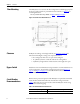
Chapter 2 Installation Floor Mounting The ProDySC is to be secured to the floor using fasteners and fittings appropriate for the type of floor. Holes are provided in the base channels; see Figure 1 for mounting dimensions. Note: Top or bottom cable entry is allowed. See Figure 1 and Figure 2 on page 9. Figure 1 - Bottom View Floor Mount Dimensions Clearance ProDySC doors hinge on both right and left. See Figure 26 on page 34 for dimensions including door swing.
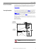
Installation Chapter 2 Electrical Terminations The ProDySC must be installed by a qualified electrician, in compliance with all local and national electric codes. The ProDySC input (line) and output (load) terminals are located behind the right door. Terminal details are shown in Figure 5 on page 12. Accessing Terminations For top entry remove the top gland plate, shown in Figure 2, to access input and output terminals. This plate may be removed for drilling or punching holes for conduit.
Chapter 2 Installation 3-Wire vs. 4-Wire Configurations ProDySC models are available for use with either 3-wire (L1, L2, L3) or 4-wire (L1, L2, L3, N) sources. The input N conductor must be connected to 4-wire models for proper operation. Do not connect a N conductor to 3-wire models. 3- Wire Models Bulletin 1608P part numbers containing V3 are configured for 3-wire source (L1, L2, L3) and 3-wire loads (X1, X2, X3). Do not connect a N conductor to 3-wire models.
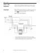
Installation 4- Wire Models Chapter 2 Bulletin 1608P part numbers containing V4 are configured for 4-wire source (L1, L2, L3, N) and either 3-wire or 4-wire loads. The source N conductor must be connected for proper operation of these models. Connect both input and output N conductors to the bus bar labeled NEUTRAL (See Figure 5). Figure 4 shows the 4-wire ProDySC system wiring schematically, including the recommended Bypass Switch. Figure 4 - ProDySC 4-Wire Configuration.
Chapter 2 Installation Electrical Terminations and Ratings Input terminal blocks are marked L1, L2, and L3 for the source connections. Output terminal blocks are marked X1, X2, and X3 for the load connections (See Figure 5). In 4-wire models only, connect both input and output N conductors to the NEUTRAL bus bar. Do not connect to the NEUTRAL bus bar in 3-wire models. The door must be closed and latched securely when the wiring is completed.
Chapter 3 Communications Both dry contacts (relays) that indicate status and a Serial Communications Port (RS-232) are available for monitoring the ProDySC. Dry Contacts Three relay contacts indicate ProDySC status. The contacts are form A and close upon occurrence of the named event: (a) any SAG EVENT, when rms input voltage drops below 88.5% of rated value; (b) OUTPUT OK, when output voltage remains between 87% and 110%; and (c) a system ALARM event. The relay contact ratings are 24V at 1A.
Chapter 3 Communications Serial Communications Port The ProDySC serial port is a DE-9 female connector. The pin-out follows standard RS-232 protocol: pin 2 is RxD, pin 3 is TxD and pin 5 is common (return). All other pins are unused. Contacts are galvanically isolated from the system power and grounds. • Protection: The RS-232 port is ESD-protected to 15kV. • Protocol: 57.6k bps, 8 data bits, one stop bit, no parity, flow control off • Data packets are SLIP encoded (with 2 byte length field).
Chapter 4 Applying Power • Before applying power to the ProDySC, make certain there are no metal filings or any conductive debris in or on any components inside the ProDySC. • Verify ProDySC voltage rating matches ac source voltage. • Ensure that all input/output wiring including grounding has been completed, all covers are replaced, and that access doors are closed and locked. • Place the ProDySC internal circuit breaker in the OFF position. • Apply power from the upstream branch protection device.
Chapter 4 Applying Power Notes: 16 Rockwell Automation Publication 1608P-UM003A-EN-P - September 2013
Chapter 5 Display Screen Overview The ProDySC® touch screen display is a window to voltage sags and ProDySC protection. The display provides system status, voltage sag notification and history, runtime statistics and system history in a simple and intuitive touchbased user interface. When the system first starts, a welcome screen displaying the ProDySC product logo appears. This screen disappears after 5 seconds, when the “Home” screen appears.
Chapter 5 Display Screen Note: To recalibrate from any screen, hold anywhere on the screen for 10 seconds. You will see a small progress bar at the bottom of the screen. When the progress bar reaches 100 percent, the calibration screen will open. Step 3: The "Touch Screen Figure 10 - Touch Screen Calibration Calibration" screen will then appear (See Figure 10). Press and hold on the center of the touch target, release when the touch target begins to flash. Repeat with the next two touch targets.
Display Screen Home Screen Chapter 5 The "HOME" screen of the display provides a snapshot view of the status of the entire system (See Figure 12). You can return to this screen from any other screen by pressing the "HOME" button. After 5 minutes of inactivity (i.e. not pressing the screen), the touch screen will automatically return to the “HOME” screen. The “HOME” screen is divided into four main areas described inTable 2.
Chapter 5 Display Screen Table 3 - System Status Description Description System Status Function Phase Status Overall system status including current operational status, availability to correct sags, and internal cabinet temperature Voltage, current, frequency, and static switch temperature are displayed for all phases. The percentage displayed following the voltage and current is the percent of nominal value for the ProDySC. Nominal values are listed on the “View Model Information” screen.
Display Screen Voltage Sag Detail Chapter 5 Voltage Sag Detail" screen (See Figure 16) displays all information related to the selected event. Details for the most recent sag event can also be accessed by pressing anywhere in the Last Voltage Sag area of the HOME screen. The worst-case RMS voltage recorded during the event is displayed in the upper window along with the corresponding voltage percentage and the event duration. Table 7 describes the remaining screen content.
Chapter 5 Display Screen Voltage Sag RMS Voltage Charts The line and load RMS voltage (L-N) of each phase is recorded for 8 cycles prior to the start of the voltage sag followed by the first 300 cycles of the voltage sag (See Figure 17). Reach this screen by pressing "CHARTS" on the "Voltage Sag Detail" screen as shown in Figure 16 on page 21. Figure 17 - - RMS Voltage Charts Line voltage is shown in red and load voltage is shown in green.
Display Screen System Events Chapter 5 The ProDySC tracks all operational events which are classified into five groups based on severity. Table 6 - System Event Description Description Function Informational Purely informational. No action is required. Auto-Resetting The PRODySC will reset within 60 seconds. No user action is required. User Attention User action may be required to correct a problem. The PRODySC will reset 60 seconds after the error condition is corrected.
Chapter 5 Display Screen System Event Detail The "System Event Detail" screen is displayed when a specific system event is selected by pressing on the "SELECT" button on the "SYSTEM EVENT LOG" screen (See Figure 19 on page 23). It provides detailed information that was recorded during the event (See Figure 20). Figure 20 - System Event Detail Table 8 - System Event Detail Description Time/Duration 24 Function Time: Date and start time of the system event Duration: The amount of time the event lasted.
Display Screen Chapter 5 System Event Notification When the ProDySC system first detects an event condition, the "System Fault Detection" dialog box will be displayed (See Figure 21). Within the "System Fault Detection" box, the name, severity, and location of the event will be displayed. Figure 21 - System Fault Detection Pressing the "OK" button will open the "System Event Detail" screen. The event will appear in the event list after the event is over.
Chapter 5 Display Screen System Configuration Press the "CONFIG" button at the bottom of the “HOME” screen to enter the “System Configuration” screen (See Figure 23). The “SET SYSTEM CLOCK” and “CALIBRATE TOUCH SENSOR” functions are described at the start of this chapter. Figure 23 - System Configuration Model Information Touch “VIEW MODEL INFORMATION” to go to the “Model Information” screen. (See Figure 24).
Display Screen Chapter 5 Run System Tests Press the "RUN SYSTEM TESTS" to enter the “System Tests” screen. Press “2 MINS” to run the system fans for 2 minutes (See Figure 25). Figure 25 - System Tests Diagnostics Mode This is not a user function. It is numerical code protected for authorized service personnel.
Chapter 5 Display Screen Notes: 28 Rockwell Automation Publication 1608P-UM003A-EN-P - September 2013
Chapter 6 Maintenance Preventative Maintenance The ProDySC requires very little preventative maintenance. The ProDySC should be checked periodically for proper air flow and status indicator operation. Monthly Checks • Ensure the touch screen display is working and no active events are displayed. • Update system time, if needed, Figure 11 on page 18. • Use a soft cloth to clean the touch display. DO NOT USE harsh detergent, abrasive sponges, alcohol, ammonia, toluene, or acetone on the touch display.
Chapter 6 Maintenance Table 10 - System Event Table Event Code 1 Code Name POWER_ON Full Name DySC Power On Severity Area Informational Unit Event Description Event Resolution Power re-applied to the DySC. No action needed. 4 T_FAN_ST Fan Test Start Informational Unit Start acknowledgment of DySC fan test. No action needed. 5 T_IN_ST_1 Inverter Test (.5 cycles) Start Informational Unit Start acknowledgment of DySC 0.5 cycle inverter test. No action needed.
Chapter 6 Event Code 42 Maintenance Code Name SRL_DIFF Full Name Start-Up Test: Serial Number Mismatch Severity Informational Area Unit Event Description Controller serial number mismatch detected during start-up test. Event Resolution No action needed. 44 46 T_INV_TO Inverter Test Timeout Call Service Unit Phase control board failed to respond to Comm board's Inverter test. Call service. DOOR_OPEN DySC Cabinet Door Open Manual Reset Unit DySC door was opened. Mechanical bypass commanded.
Chapter 6 Maintenance Replace fuse with the same type or equivalent cross-referenced rating. You may order these fuses through Rockwell Automation or the manufacturer listed.
Chapter 7 Specifications and Dimensions Table 12 - Technical Specifications 200 A ProDySC Electrical Input/Output (Normal Mode—Static Switch) Connection Configuration Series-connected with load. Under normal line condition, the static switch passes utility voltage directly to the load Standard Input Voltages 3-phase: 208, 380, 400, 415, 480V1 Voltage Range ± 10% Current Overload (Static Switch) 150% @ 30Sec., 400% @ 5 Sec., 600% @ 0.5 Sec.
Chapter 7 Specifications and Dimensions Table 13 - Heat Dissipation Rating (V) 208V 480V Approximate Dimensions Heat Loss (W) 1035 1325 Heat Loss (Btu/h) 3534 4524 Dimensions are shown in inches (millimeters). Dimensions are not intended to be used for manufacturing purposes. Figure 26 - 200 A ProDySC Dimensions 0,1,080 > @ &/($5$1&( 72 %( 0$,17$,1(' )520 6,'( $1' %$&.
Rockwell Automation Support Rockwell Automation provides technical information on the Web to assist you in using its products. At http://www.rockwellautomation.com/support, you can find technical manuals, technical and application notes, sample code and links to software service packs, and a MySupport feature that you can customize to make the best use of these tools. You can also visit our Knowledgebase at http://www.rockwellautomation.