
User Manual, 100/110 A User Manual


14 Rockwell Automation Publication 1608P-UM002A-EN-P - July 2013
Chapter 2 Installation
Bypass Terminations
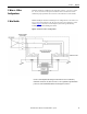
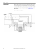
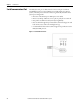
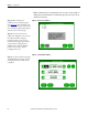
The recommended bypass switch input and output terminals are located inside
the bypass enclosure. All terminals are labeled and a wiring diagram is provided
inside the door, as shown in Figure
. The numbered switch positions correspond
to the numbered modes in Figure 2
. The N terminals should not be used with 3-
wire ProDySC models.
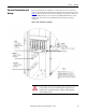
Bypass Connection