Installation Instructions Bulletin 1608P ProDySC Dynamic Voltage Sag Corrector Cat. No. 1608P....
Important User Information Solid-state equipment has operational characteristics differing from those of electromechanical equipment. Safety Guidelines for the Application, Installation and Maintenance of Solid State Controls (publication SGI-1.1 available from your local Rockwell Automation sales office or online at http://www.rockwellautomation.com/literature/) describes some important differences between solid-state equipment and hard-wired electromechanical devices.
Table of Contents Ch 1 - Introduction Ch 2- Installation Ch 3- Communications Important User Information . . . . . . . . . . . . . . . . . . . . . . . . . . . . . . . . . . . . . . . . . . . . . .2 Additional Resources. . . . . . . . . . . . . . . . . . . . . . . . . . . . . . . . . . . . . . . . . . . . . . . . . . . . . 2 Safety Considerations . . . . . . . . . . . . . . . . . . . . . . . . . . . . . . . . . . . . . . . . . . . . . . . . . . . . .5 Installation Check List . . . . . . . . . . . . . . .
Table of Contents Notes: 4 Rockwell Automation Publication 1608P-IN002B-EN-P - May 2014
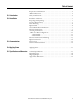
Chapter 1 Introduction The Allen-Bradley Bulletin 1608P ProDySC Dynamic Sag Corrector is engineered to provide years of trouble-free voltage sag (dip) protection. The patented DySC technology does not use batteries, requires only routine maintenance, includes three-stage transient voltage surge suppression, and has unparalleled energy efficiency. Most electronic devices found in industry today are susceptible to power disturbances.
Chapter 1 ATTENTION: Internal components can be easily damaged by electrostatic discharge (ESD). Do not touch circuit boards or electronic components with hands or metal objects. Use an insulated screw driver when connecting the lines. • The ProDySC is not rated to directly power life support equipment. • Ensure the area around the ProDySC is clean and uncluttered. • Observe all DANGER, CAUTION, and WARNING notices affixed to the inside and outside of the equipment.
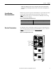
Chapter 2 Installation Installation Check List Inspecting and Unpacking Location (Environment) Before proceeding, please take a few minutes to review the necessary steps to install your ProDySC. • All packing materials and restraints have been removed. • The ProDySC is placed in its installed location. • All conduits and cables are properly routed to the ProDySC. • All power cables are properly terminated. • A ground conductor is properly installed and terminated.
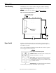
Chapter 2 Installation Floor Mounting The ProDySC is to be secured to the floor using 3/8” hardware and fittings appropriate for the type of floor. Holes are provided in the base channels; see Figure 1 for mounting dimensions. Note: Top or bottom cable entry is allowed. SeeFigure 1 and Figure 4 on page 10. Figure 1 - Bottom View Floor Mount Dimensions MOUNTING HOLE .63 (4 PLACES) 16 21.0 533 ALTERNATE POWER ACCESS 1.1 28 26.4 671 Bypass Switch 1.
Installation Chapter 2 NOTICE: The 1608P bypass switch contacts are designed to make-before-break and will not disrupt power to the load during any mode transitions. The switch has lockout/tagout (LOTO) provisions. Circuit Breaker Recommendations Branch circuit protection upstream of the ProDySC is required. Recommended circuit breakers and maximum allowed circuit breaker ratings are listed in Table 1. Branch circuit protection rated less than the ProDySC current rating may result in nuisance tripping.
Chapter 2 Installation Accessing Terminations For top entry remove the top gland plate, shown in Figure 4, to access input and output terminals. This plate may be removed for drilling or punching holes for conduit. Alternate bottom entry should utilize the bottom gland plate shown in Figure 1. Access to the communications port is only from the top, as shown in Figure 4. A separate conduit knock-out is provided for communications conductors.
Installation Chapter 2 3-Wire vs. 4-Wire Configurations ProDySC models are available for use with either 3-wire (L1, L2, L3) or 4-wire (L1, L2, L3, N) sources. The input N conductor must be connected to 4-wire models for proper operation. Do not connect a N conductor to 3-wire models. 3- Wire Models Bulletin 1608P part numbers containing V3 are configured for 3-wire source (L1, L2, L3) and 3-wire loads (X1, X2, X3). Do not connect a N conductor to 3-wire models.
Chapter 2 Installation 4- Wire Models Bulletin 1608P part numbers containing V4 are configured for 4-wire source (L1, L2, L3, N) and either 3-wire or 4-wire loads. The source N conductor must be connected for proper operation of these models. Connect both input and output N conductors to the bus bar labeled NEUTRAL (See Figure 7). Figure 6 shows the 4-wire ProDySC system wiring schematically, including the recommended Bypass Switch. Figure 6 - ProDySC 4-Wire Configuration.
Installation Electrical Terminations and Ratings Chapter 2 Input terminal blocks are marked L1, L2, and L3 for the source connections. Output terminal blocks are marked X1, X2, and X3 for the load connections (See Figure 7). In 4-wire models only, connect both input and output N conductors to the NEUTRAL bus bar. Do not connect to the NEUTRAL bus bar in 3-wire models. The door must be closed and latched securely when the wiring is completed.
Chapter 2 Installation Bypass Terminations The recommended bypass switch input and output terminals are located inside the bypass enclosure. All terminals are labeled and a wiring diagram is provided inside the door, as shown in Figure 8. The numbered switch positions correspond to the numbered modes in Figure 2. The N terminals should not be used with 3wire ProDySC models.
Chapter 3 Communications Both dry contacts (relays) that indicate status and a Serial Communications Port (RS-232) are available for monitoring the ProDySC. Dry Contacts Three relay contacts indicate ProDySC status. The contacts are form A and close upon occurrence of the named event: (a) any SAG EVENT, when rms input voltage drops below 88.5% of rated value; (b) OUTPUT OK, when output voltage remains between 87% and 110%; and (c) a system ALARM event. The relay contact ratings are 24V at 1 amp.
Chapter 3 Communications Serial Communications Port The ProDySC serial port is a DE-9 female connector. The pin-out follows standard RS-232 protocol: pin 2 is RxD, pin 3 is TxD and pin 5 is common (return). All other pins are unused. Contacts are galvanically isolated from the system power and grounds. • Protection: The RS-232 port is ESD-protected to 15kV. • Protocol: 57.6k bps, 8 data bits, one stop bit, no parity, flow control off • Data packets are SLIP encoded (with 2 byte length field).
Chapter 4 Applying Power • Before applying power to the ProDySC, make certain there are no metal filings or any conductive debris in or on any components inside the ProDySC. • Ensure that all input/output wiring including grounding has been completed and that all access doors are closed. • Place the maintenance bypass in “Bypass” mode. • Apply power from the upstream branch protection device. Power will flow through the maintenance bypass directly to the load.
Chapter 4 Applying Power Notes: 18 Rockwell Automation Publication 1608P-IN002B-EN-P - May 2014
Chapter 5 Specifications and Dimensions Table 2 - Technical Specifications 100 and 110 A ProDySC Electrical Input/Output (Normal Mode—Static Switch) Connection Configuration Series-connected with load. Under normal line condition, the static switch passes utility voltage directly to the load Standard Input Voltages 3 φ: 208, 380, 400, 415, 480V1 Voltage Range ± 10% Current Overload (Static Switch) 200% @ 30Sec., 400% @ 5 Sec., 600% @ 0.5 Sec.
Chapter 5 Specifications and Dimensions Heat Dissipation Rating (A) Heat Loss (W) Heat Loss (Btu/h) Efficiency (%) Standard Run-time (SR) 100 110 780 816 2664 2787 98.3% 98.3% Extended Run-time (ER) 100 110 1071 1107 3657 3780 97.7% 97.8% Shipping Weights Rating (A) Cat. No. Weight lbs.[kg] Standard Run-time (SR) 100 110 1608P-100A...V3S 1608P-100A...V4S 1608P-110A...V3S 1608P-110A...V4S 787 [357] 772 [351] 787 [357] 772 [351] Extended Run-time (ER) 100 110 20 1608P-100A...
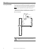
Specifications and Dimensions Approximate Dimensions Chapter 5 Dimensions are shown in inches (millimeters). Dimensions are not intended to be used for manufacturing purposes. Figure 11 - Standard Runtime 3 & 4 Wire AC INPUT/OUTPUT CONDUIT ENTRY COMMUNICATIONS PORT .875 22 COMMUNICATIONS CONDUIT KNOCK-OUT 24.7 627 52.2 1327 CLEARANCE FOR DOOR SWING 29.0 737 TOUCHSCREEN DISPLAY AIR FILTERS (FOUR PLACES) 57.
Chapter 5 Specifications and Dimensions Figure 12 - Extended Runtime 3 & 4 Wire 29.0 737 TOUCHSCREEN DISPLAY AIR FILTERS (SIX PLACES) 77.
Rockwell Automation Support Rockwell Automation provides technical information on the Web to assist you in using its products. At http://www.rockwellautomation.com/support, you can find technical manuals, technical and application notes, sample code and links to software service packs, and a MySupport feature that you can customize to make the best use of these tools. You can also visit our Knowledgebase at http://www.rockwellautomation.