
Installation Instructions, 25 and 50 A Instruction Manual


Rockwell Automation Publication 1608P-IN001B-EN-P - May 2014 11
Installation Chapter 2
Bypass Switch
Wiring Diagram
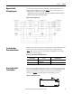
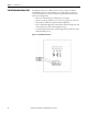
The maintenance bypass has input and output terminals labeled and located
inside the bypass enclosure as shown in Figure 5
. The neutral connection is
available for 4-wire ProDySC configurations.
NOTICE: All electrical connections must be completed by a qualified electrician, in compliance
with all local codes and the National Electric Code.
Figure 5 - Bypass wiring diagram
Circuit Breaker
Recommendations
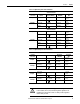
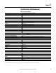
Branch circuit protection upstream of the ProDySC is required. Recommended
circuit breakers and maximum allowed circuit breaker ratings are listed in
Table 1
. Branch circuit protection rated less than the ProDySC current rating
may result in nuisance tripping.
Table 1 - Recommended Branch Circuit Protection
Accessing ProDySC
Terminations
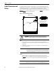
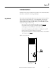
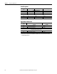
Two holes are provided for punch-out locations to provide the appropriate hole
size for conduit fittings in the ProDySC. Take care to avoid dropping any metal
filings inside the enclosure. Metallic contamination will void the product
warranty. See Figure 6
for preferred Input/Output wiring locations.
Figure 6 - Knockout Hole Locations
ProDySC Rating
Recommended MCCB
Cat. No.
Max. MCCB Rating
25 A 140U-H3C3-C35 35 A
50 A 140U-H6C3-C70 70 A
2X
1.12
28
TOP VIEW