Installation Instructions Bulletin 1608P ProDySC Dynamic Voltage Sag Corrector Catalog Numbers 1608P - 25 and 50 Amp Models
Important User Information Solid-state equipment has operational characteristics differing from those of electromechanical equipment. Safety Guidelines for the Application, Installation and Maintenance of Solid State Controls (publication SGI-1.1 available from your local Rockwell Automation sales office or online at http://www.rockwellautomation.com/literature/) describes some important differences between solid-state equipment and hard-wired electromechanical devices.
Table of Contents Ch 1 - Introduction Ch 2 - Installation Important User Information . . . . . . . . . . . . . . . . . . . . . . . . . . . . . . . . . . . . . . . 2 Additional Resources . . . . . . . . . . . . . . . . . . . . . . . . . . . . . . . . . . . . . . . . . . . . . . 2 Safety Considerations . . . . . . . . . . . . . . . . . . . . . . . . . . . . . . . . . . . . . . . . . . . . . . 5 Installation Check List . . . . . . . . . . . . . . . . . . . . . . . . . . . . . . . . . . . . . . . . . . . . .
Table of Contents Notes: 4 Rockwell Automation Publication 1608P-IN001B-EN-P - May 2014
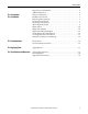
Chapter 1 Introduction The Allen-Bradley Bulletin 1608P ProDySC Dynamic Sag Corrector is engineered to provide years of trouble-free voltage sag (dip) protection. The patented ProDySC technology does not use batteries, requires only routine maintenance, includes three-stage transient voltage surge suppression, and has unparalleled energy efficiency. Most electronic devices found in industry today are susceptible to power disturbances.
Chapter 1 Introduction ATTENTION: Internal components can be easily damaged by electrostatic discharge (ESD). Do not touch circuit boards or electronic components with hands or metal objects. Use an insulated screw driver when connecting the lines. • The ProDySC is not rated to directly power life support equipment. • Ensure the area around the ProDySC is clean and uncluttered. • Observe all DANGER, CAUTION, and WARNING notices affixed to the inside and outside of the equipment.
Chapter 2 Installation Installation Check List Inspecting and Unpacking Before proceeding, please take a few minutes to review the necessary steps to install your ProDySC. • All packing materials and restraints have been removed. • The ProDySC is placed in its installed location. • All conduits and cables are properly routed to the ProDySC. • All power cables are properly terminated. • A ground conductor is properly installed and terminated.
Chapter 2 Installation Mounting the ProDySC Using the 3/8" hardware and four (4) wall mounting brackets supplied, mount the wall mount brackets to the back of the ProDySC. Mount each bracket to the back of the ProDySC with a single 3/8"-16 x 1" hex cap head screw. Mount the brackets so the flat portion of the mounting bracket is against the back of the ProDySC. Bolt two 2 x 4 pieces of lumber horizontally to the wall using 3/8" by 4" hex-head lag bolts. Make certain that: 1.
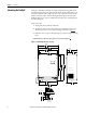
Installation Chapter 2 Figure 2 - 50A Mounting dimensions, in. [mm] 37.36 949 34.50 876 36.00 914 13.21 336 33.00 838 12.80 325 37.13 943 36.00 914 A 33.00 838 34.50 876 13.39 340 .57 TYP. 14 .75 19 1.50 38 .41 TYP.
Chapter 2 Installation Bypass Switch Installation of the ProDySC with an external maintenance bypass is required to avoid power interruptions to the critical loads during maintenance, service, or testing. Mount the bypass close to the ProDySC to provide quick access and visual coordination when testing or providing service. The 1608P bypass is a wall mounted enclosure with a 3 position rotary switch. Its dimensions and mounting locations are shown in Figure 3.
Installation Bypass Switch Wiring Diagram Chapter 2 The maintenance bypass has input and output terminals labeled and located inside the bypass enclosure as shown in Figure 5. The neutral connection is available for 4-wire ProDySC configurations. NOTICE: All electrical connections must be completed by a qualified electrician, in compliance with all local codes and the National Electric Code.
Chapter 2 Installation ProDySC Terminations and Ratings A qualified electrician must install the units. To access the ProDySC Electrical Terminations, turn the two ¼ - turn latches CCW and swing open the door. The unit is furnished with one of the terminal block configurations as shown in Figure 7. For power cable termination specifications see Table 2 for the 25A rated units andTable 3 for the 50A rated units.
Installation Chapter 2 Table 2 - ProDySC 25 Amp Power Cable Terminations 3 Wire with a Ground Terminal Connection AC Input Function Phase A, B, C Terminal Marking L1, L2, L3 Ground AC Output Phase A, B, C Wire Range AWG (mm2) 24- 8 (0.5-6) ¼-20 Stud X1, X2, X3 Ground 24-8 (0.5-6) ¼-20 Stud Torque lb-in (Nm) 7.1- 8.9 (0.8-1) 65 (7.3) 7.1- 8.9 (0.8-1) 65 (7.3) 4 Wire with a Ground AC Input Phase A, B, C L1, L2, L3 Ground AC Output 24- 8 (0.
Chapter 2 Installation Notes: 14 Rockwell Automation Publication 1608P-IN001B-EN-P - May 2014
Chapter 3 Communications Both dry contacts (relays) that indicate status and a Serial Communications Port (RS-232) are available for monitoring the ProDySC. Dry Contacts Three relay contacts indicate ProDySC status. The contacts are form A and close upon occurrence of the named event: (a) any SAG EVENT, when rms input voltage drops below 88.5% of rated value; (b) OUTPUT OK, when output voltage remains between 87% and 110%; and (c) a system ALARM event. The relay contact ratings are 24V at 1 amp.
Chapter 3 Communications Serial Communications Port The ProDySC serial port is a DE-9 female connector. The pin-out follows standard RS-232 protocol: pin 2 is RxD, pin 3 is TxD and pin 5 is common (return). All other pins are unused. Contacts are galvanically isolated from the system power and grounds. • Protection: The RS-232 port is ESD-protected to 15kV • Protocol: 57.
Chapter 4 Applying Power • Verify that the ProDySC voltage rating matches the source voltage. • Before applying power to the ProDySC, make certain there are no metal filings or any conductive debris in or on any components inside the ProDySC. • Ensure that all input/output wiring including grounding has been completed and that all access doors are closed. • Place the maintenance bypass in “Bypass” mode. • Apply power from the upstream branch protection device.
Chapter 4 Applying Power Notes: 18 Rockwell Automation Publication 1608P-IN001B-EN-P - May 2014
Chapter 5 Specifications and Dimensions Table 4 - Technical Specifications Electrical Input/Output (Normal Mode—Static Switch) Connection Configuration Series-connected with load. Under normal line condition, the static switch passes utility voltage directly to the load Standard Input Voltages 3 : 208, 380, 400, 415, 480V1 Voltage Range ± 10% Current Overload (Static Switch) 150% @ 30Sec., 400% @ 5 Sec., 600% @ 0.5 Sec.
Chapter 5 Specifications and Dimensions Heat Dissipation Rating (A) 25 50 Heat Loss (W) Heat Loss (Btu/h) Standard Run-time (SR) 957 1196 280 350 Efficiency (%) 97.8% 97.2% Extended Run-time (ER) 25 50 420 560 1435 1913 98.2% 97.7% Approximate Dimensions Rating (A) 25 50 HxWxD in. [mm] Standard Run-time (SR) 32 x 26 x 14 [813 x 660 x 356] 38 x 38 x 14 [965 x 965 x 356] Extended Run-time (ER) Weight lbs.
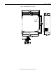
Specifications and Dimensions Chapter 5 Figure 10 - 25AStandard/Extended Run 25.35 644 22.50 572 24.00 610 13.21 336 21.00 533 12.80 325 31.13 791 30.00 762 21.00 533 A 22.50 572 13.39 340 .57 TYP. 14 .75 19 1.50 38 .41 TYP.
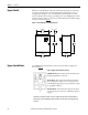
Chapter 5 Specifications and Dimensions Figure 11 - 50A Standard/Extended Run 37.36 949 34.50 876 36.00 914 13.21 336 33.00 838 12.80 325 37.13 943 36.00 914 A 33.00 838 34.50 876 .57 TYP. 14 .75 19 1.50 38 .41 TYP. 10 DETAIL A 4 PLACES 22 Rockwell Automation Publication 1608P-IN001B-EN-P - May 2014 13.
Rockwell Automation Support Rockwell Automation provides technical information on the Web to assist you in using its products. At http://www.rockwellautomation.com/support, you can find technical manuals, technical and application notes, sample code and links to software service packs, and a MySupport feature that you can customize to make the best use of these tools. You can also visit our Knowledgebase at http://www.rockwellautomation.