
Installation Instructions, 200 A Owner manual


8 Rockwell Automation Publication 1608P-UM004A-EN-P - September 2013
Chapter 2 Installation
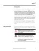
Floor Mounting
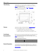
The HC-DySC is to be secured to the floor using fasteners and fittings
appropriate for the type of floor. Holes are provided in the base channels; see
Figure 1
for mounting dimensions.
Note: Top or bottom cable entry is allowed. See Figure 1
and Figure 2 on page 9.
Figure 1 - Bottom View Floor Mount Dimensions
Clearance
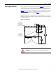
HC-DySC doors hinge on both right and left. See Figure 10 on page 20 for
dimensions including door swing. Leave required clearances:
• Door swing must allow doors to open at least 90 degrees
• 12” [300mm] clearance on left side and rear for cooling airflow
• 4”[100mm] on right side for air filter clearance when right door opens
Circuit Breaker
Recommendations
Branch circuit protection upstream of the HC-DySC is required. Recommended
circuit breakers and maximum allowed circuit breaker ratings are listed in
Tabl e 1
. Branch circuit protection rated less than the HC-DySC current rating
may result in nuisance tripping.
Table 1 - Recommended Branch Circuit Protection
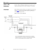
Electrical Terminations
The HC-DySC must be installed by a qualified electrician, in compliance with
all local and national electric codes. The HC-DySC input (line) and output
(load) terminals are located behind the right door. Terminal details are shown in
Figure 5 on page 12
.
HC-DySC Rating Max. MCCB Rating
200 A 250 A